Toyota Tacoma (2015-2018) Service Manual: Installation
INSTALLATION
PROCEDURE
1. INSTALL TRANSFER ASSEMBLY
Click here .gif)
2. INSTALL WIRING HARNESS CLAMP BRACKET
(a) Install the 4 wiring harness clamp brackets with the 4 bolts.
Torque:
8.0 N·m {82 kgf·cm, 71 in·lbf}
3. INSTALL TRANSMISSION BREATHER SUB-ASSEMBLY
(a) Install the 2 brackets to the manual transmission assembly with the 2 bolts.
Torque:
19 N·m {194 kgf·cm, 14 ft·lbf}
(b) Install the transmission breather sub-assembly to the control shift lever retainer assembly.
(c) Attach the 3 breather hose clamps.
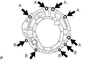
4. INSTALL MANUAL TRANSMISSION ASSEMBLY
|
(a) Install the manual transmission assembly with the 9 bolts. Torque: Bolt A : 72 N·m {730 kgf·cm, 53 ft·lbf} Bolt B : 37 N·m {380 kgf·cm, 28 ft·lbf} |
|
5. CONNECT WIRE HARNESS
(a) Attach the 10 clamps to install the wire harness.
(b) Connect the 3 connectors.
6. INSTALL REAR NO. 1 ENGINE MOUNTING INSULATOR
(a) Install the rear engine mounting insulator to the manual transmission assembly with the 4 bolts.
Torque:
58 N·m {591 kgf·cm, 43 ft·lbf}
7. INSTALL NO. 3 FRAME CROSSMEMBER SUB-ASSEMBLY
(a) Install the No. 3 frame crossmember sub-assembly with the 4 nuts and 4 bolts.
Torque:
40 N·m {408 kgf·cm, 30 ft·lbf}
(b) Install the 4 bolts to the No. 3 frame crossmember sub-assembly.
Torque:
21 N·m {214 kgf·cm, 15 ft·lbf}
8. INSTALL FRONT SUSPENSION MEMBER BRACKET LH AND RH
(a) Install the front suspension member bracket LH and front suspension member bracket RH to the No. 3 frame crossmember sub-assembly and vehicle body with the 8 bolts.
Torque:
33 N·m {337 kgf·cm, 24 ft·lbf}
9. INSTALL FRONT DIFFERENTIAL CARRIER ASSEMBLY
Click here
10. INSTALL PROPELLER SHAFT WITH CENTER BEARING ASSEMBLY
Click here
11. INSTALL STARTER ASSEMBLY
Click here
12. INSTALL NO. 2 MANIFOLD STAY
Click here
13. INSTALL MANIFOLD STAY
Click here
14. INSTALL FRONT EXHAUST PIPE ASSEMBLY
Click here
15. ADD MANUAL TRANSMISSION OIL
Click here
16. INSTALL NO. 1 FLOOR SHIFT BUSH
(a) Install the No. 1 floor shift bush to the floor shift shift lever assembly.
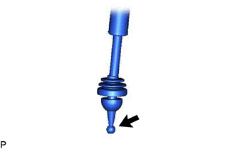
17. INSTALL FLOOR SHIFT SHIFT LEVER ASSEMBLY
(a) Apply MP grease to the tip of the floor shift shift lever assembly.
 Text in Illustration
.png) |
MP grease |
|
(b) Cover the shift lever cap with a cloth. Text in Illustration
|
|
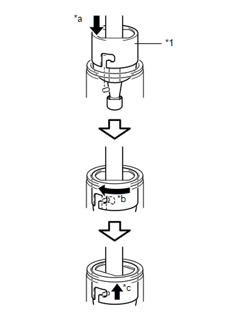
(c) While pressing down on the shift lever cap, turn it clockwise to install the shift lever assembly.
(d) Attach the shift lever cap boot to the manual transmission.
18. INSTALL SHIFT LEVER BOOT ASSEMBLY
(a) Install the shift lever boot assembly with the 2 screws and 2 clips.
19. INSTALL FRONT CONSOLE BOX
Click here
20. CONNECT CABLE TO NEGATIVE BATTERY TERMINAL
Torque:
5.4 N·m {55 kgf·cm, 48 in·lbf}
NOTICE:
When disconnecting the cable, some systems need to be initialized after the cable is reconnected.
Click here
 Components
COMPONENTS
ILLUSTRATION
ILLUSTRATION
...
 Removal
REMOVAL
PROCEDURE
1. PRECAUTION
NOTICE:
After turning the ignition switch off, waiting time may be required before disconnecting
the cable from the negative (-) battery terminal. Therefore, make ...
Other materials:
System Description
SYSTEM DESCRIPTION
1. ENGINE IMMOBILISER SYSTEM DESCRIPTION
The engine immobiliser system is designed to prevent the vehicle from being stolen.
This system uses the transponder key ECU assembly that stores the key ID codes of
authorized ignition keys. If an attempt is made to start the engine ...
Inspection
INSPECTION
PROCEDURE
1. INSPECT CAMSHAFT TIMING OIL CONTROL SOLENOID ASSEMBLY
(a) Check the operation.
(1) Apply battery voltage between the terminals and check that the plunger
operates.
Text in Illustration
*a
Component without harness con ...
System Description
SYSTEM DESCRIPTION
1. WIRELESS DOOR LOCK CONTROL SYSTEM
The wireless door lock control system can be used to lock and unlock all doors
from a distance. The system is controlled by an electrical key transmitter sub-assembly
which sends radio waves to the door control receiver. The certification ...
