Toyota Tacoma (2015-2018) Service Manual: Removal
REMOVAL
PROCEDURE
1. PRECAUTION
NOTICE:
After turning the ignition switch off, waiting time may be required before disconnecting the cable from the negative (-) battery terminal.
Therefore, make sure to read the disconnecting the cable from the negative (-) battery terminal notices before proceeding with work.
Click here .gif)
2. DISCONNECT CABLE FROM NEGATIVE BATTERY TERMINAL
NOTICE:
When disconnecting the cable, some systems need to be initialized after the cable is reconnected.
Click here
3. REMOVE REAR WHEEL
4. DRAIN BRAKE FLUID
5. REMOVE REAR BRAKE DRUM SUB-ASSEMBLY
Click here
6. REMOVE FRONT BRAKE SHOE
Click here
7. REMOVE REAR BRAKE SHOE
Click here
8. REMOVE REAR SPEED SENSOR
Click here
9. SEPARATE PARKING BRAKE CABLE ASSEMBLY NO. 3
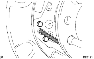
(a) Remove the 2 bolts and disconnect the parking brake cable from the backing plate.
10. SEPARATE REAR BRAKE TUBE NO. 8
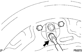
(a) Using a union nut wrench, separate the brake tube, and use a container to catch the brake fluid as it flows out.
11. REMOVE REAR AXLE SHAFT WITH BACKING PLATE
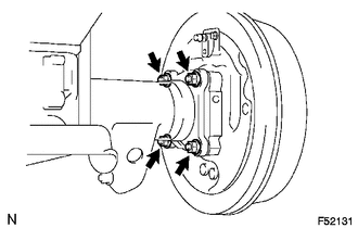
(a) Remove the 4 nuts and rear axle shaft with backing plate.
(b) Remove the O-ring.
12. REMOVE REAR AXLE SHAFT OIL SEAL
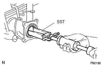
(a) Using SST, remove the oil seal.
SST: 09308-00010
 Inspection
INSPECTION
PROCEDURE
1. INSPECT REAR AXLE SHAFT
(a) Using a dial indicator, measure the runout of the shaft and flange.
Maximum runout:
Shaft runout: 1.5 mm (0.0591 in.)
Flange runout: 0.05 m ...
 Installation
INSTALLATION
PROCEDURE
1. INSTALL REAR AXLE SHAFT OIL SEAL
(a) Using SST and a hammer, install a new oil seal.
SST: 09950-60020
09951-00770
SST: 09950-70010
09951-07150
2. INSTALL REAR AXLE ...
Other materials:
Problem Symptoms Table
PROBLEM SYMPTOMS TABLE
If a normal code is displayed during the DTC check but the problem still occurs,
check the circuits for each problem symptom in the order given in the table below
and proceed to the relevant troubleshooting page.
NOTICE:
When replacing the skid control ECU (master cylin ...
Diagnostic Trouble Code Chart
DIAGNOSTIC TROUBLE CODE CHART
HINT:
If a trouble code is displayed during the DTC check, inspect the trouble areas
listed for that code. For details of the code, refer to the "See page" below.
Lighting system
DTC Code
Detection Item
See page
...
Installation
INSTALLATION
PROCEDURE
1. INSTALL HAZARD WARNING SIGNAL SWITCH ASSEMBLY (AIR CONDITIONING CONTROL ASSEMBLY)
(for Automatic Air Conditioning System)
(a) Connect the connectors.
(b) Engage the 8 clips to hazard warning signal switch assembly (air conditioning
control assembly).
2. INSTALL HAZ ...
