Toyota Tacoma (2015-2018) Service Manual: Engine Hood Courtesy Switch
Components
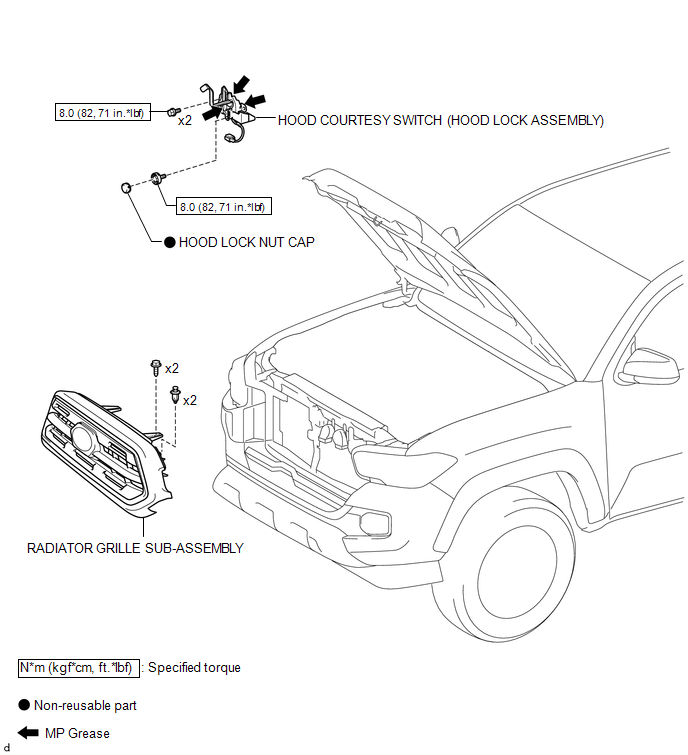
COMPONENTS
ILLUSTRATION
Inspection
INSPECTION
PROCEDURE
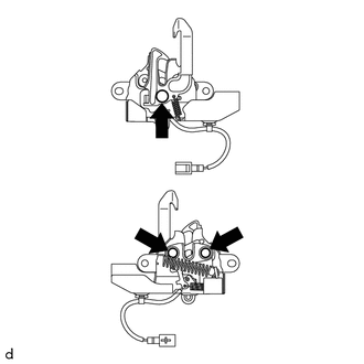
1. INSPECT HOOD COURTESY SWITCH (HOOD LOCK ASSEMBLY)
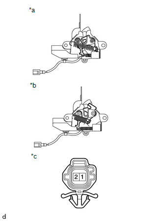
(a) Check the resistance.
|
(1) Measure the resistance according to the value(s) in the table below. Text in Illustration
Standard Resistance:
If the results are not as specified, replace the hood courtesy switch (hood lock assembly). |
|
Removal
REMOVAL
PROCEDURE
1. REMOVE RADIATOR GRILLE SUB-ASSEMBLY
(See page .gif) )
)
2. REMOVE HOOD COURTESY SWITCH (HOOD LOCK ASSEMBLY)
|
(a) Disconnect the connector. |
|
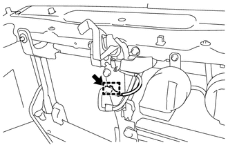
(b) Disengage the clamp to separate the wire harness.
|
(c) Using a screwdriver with its tip wrapped in protective tape, remove the hood lock nut cap. Text in Illustration
|
|

|
(d) Remove the 3 bolts to separate the hood courtesy switch (hood lock assembly). |
|
.png)
|
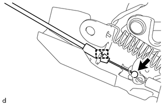
(e) Disengage the guide to disconnect the hood lock control cable assembly and remove the hood courtesy switch (hood lock assembly). |
|
Installation
INSTALLATION
PROCEDURE
1. INSTALL HOOD COURTESY SWITCH (HOOD LOCK ASSEMBLY)
|
(a) Apply MP grease to the sliding areas of the hood courtesy switch (hood lock assembly). |
|
(b) Engage the guide to connect the hood lock control cable assembly.
(c) Install the hood courtesy switch (hood lock assembly) with the 3 bolts.
Torque:
8.0 N·m {82 kgf·cm, 71 in·lbf}
(d) Install a new hood lock nut cap.
(e) Connect the connector.
(f) Engage the clamp to install the wire harness.
2. ADJUST HOOD SUB-ASSEMBLY
(See page .gif) )
)
3. INSTALL RADIATOR GRILLE SUB-ASSEMBLY
(See page
)
 Theft Deterrent
...
 Security Horn Assembly
Components
COMPONENTS
ILLUSTRATION
Inspection
INSPECTION
PROCEDURE
1. INSPECT SECURITY HORN ASSEMBLY
(a) Check the operation.
(1) Apply battery voltage and check operation o ...
Other materials:
Parts Location
PARTS LOCATION
ILLUSTRATION
ILLUSTRATION
ILLUSTRATION
ILLUSTRATION
ILLUSTRATION
...
Open in ABS Solenoid Relay Circuit (C146E,C146F)
DESCRIPTION
The ABS solenoid relay supplies power to the ABS solenoid and TRAC solenoid.
The solenoid relay is turned on 1.5 seconds after the ignition switch is turned
ON, and is turned off if an open or short in the solenoid is detected by the self
diagnosis performed when the engine starts ...
Perchlorate Material
Special handling may apply, See www.dtsc.ca.gov/hazardouswaste/perchlorate.
Your vehicle has components that may contain perchlorate. These components may
include airbag, seat belt pretensioners, and wireless remote control batteries.
CAUTION
■General precautions while driving
Driving un ...
