Toyota Tacoma (2015-2018) Service Manual: Reassembly
REASSEMBLY
CAUTION / NOTICE / HINT
CAUTION:
Wear protective gloves. Sharp areas on the parts may injure your hands.
PROCEDURE
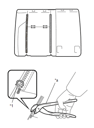
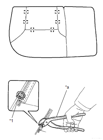
1. INSTALL SEPARATE TYPE REAR SEATBACK COVER
|
(a) Using hog ring pliers, install the separate type rear seatback cover with 2 new hog rings. Text in Illustration
NOTICE:
|
|
(b) Engage the 2 hook-and-loop fasteners.
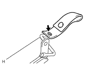
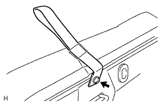
2. INSTALL REAR SEAT LOCK HANDLE
|
(a) Install the rear seat lock handle with the screw. |
|
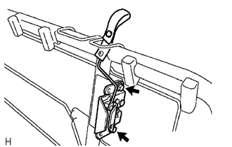
3. INSTALL REAR SEATBACK LOCK ASSEMBLY
|
(a) Install the rear seatback lock assembly with the 2 bolts. Torque: 30 N·m {306 kgf·cm, 22 ft·lbf} |
|
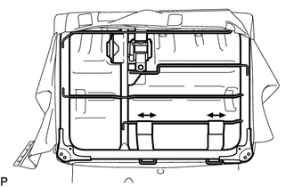
4. INSTALL REAR CENTER SEAT OUTER BELT ASSEMBLY
.gif)
5. INSTALL CENTER SEATBACK PAD
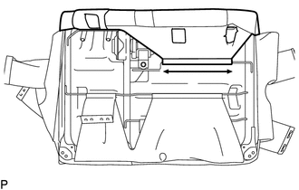
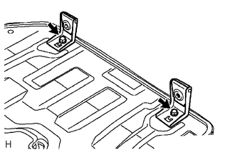
6. INSTALL REAR SEATBACK FRAME SUB-ASSEMBLY
|
(a) Engage the 2 hooks to install the rear seatback frame sub-assembly. |
|
|
(b) Engage the 2 hooks. |
|
7. INSTALL REAR SEAT SHOULDER BELT COVER
|
(a) Engage the 4 claws to install the rear seat shoulder belt cover. |
|
8. INSTALL SEAT BELT ANCHOR COVER CAP
|
(a) Engage the 2 claws to install the seat belt anchor cover cap. |
|
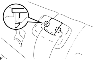
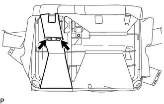
9. INSTALL REAR NO. 1 SEAT HEADREST SUPPORT ASSEMBLY
|
(a) Engage the protrusion of the rear No. 1 seat headrest support assemblies with the groove in the installation portion of the rear seatback frame sub-assembly. Text in Illustration
|
|
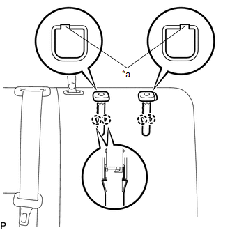
(b) Engage the 4 claws to install the 2 rear No. 1 seat headrest support assemblies.
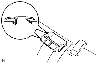
10. INSTALL REAR SEAT HEADREST SUPPORT
|
(a) Engage the 4 claws to install the 2 rear seat headrest supports. |
|
.png)
|
(b) Engage the hook. |
|
|
(c) Connect the rear seatback cover strap. |
|
|
(d) Connect the 2 rear seatback cover straps. |
|
11. INSTALL REAR SEATBACK BOARD SUB-ASSEMBLY
|
(a) Engage the 5 claws and install the rear seatback board sub-assembly. |
|
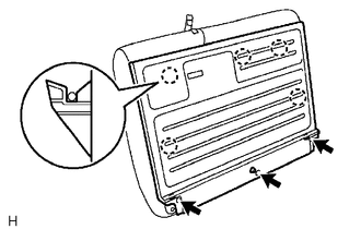
(b) Install the 3 screws.
12. INSTALL REAR SEAT HEADREST ASSEMBLY
(a) Disengage the 2 lock buttons of the 2 rear seat headrest supports to install the rear seat headrest assembly.
13. INSTALL REAR CENTER SEAT HEADREST ASSEMBLY
(a) Disengage the lock button of the rear No. 1 seat headrest support assembly to install the rear center seat headrest assembly.
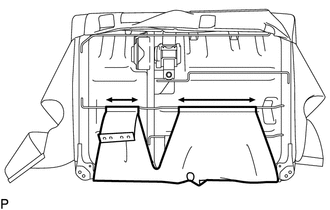
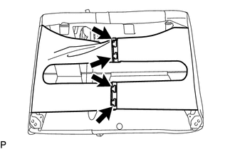
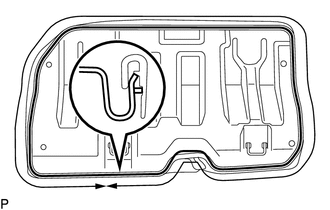
14. INSTALL SEPARATE TYPE REAR SEAT CUSHION COVER
|
(a) Using hog ring pliers, install the separate type rear seat cushion cover with 6 new hog rings. Text in Illustration
NOTICE:
|
|
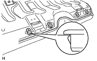
15. INSTALL REAR SEAT CUSHION FRAME SUB-ASSEMBLY
|
(a) Engage the hook and install the rear seat cushion frame sub-assembly. |
|
16. INSTALL REAR SEAT CUSHION HINGE SUB-ASSEMBLY
|
(a) Install the 2 rear seat cushion hinge sub-assemblies with the 2 bolts. Torque: 21 N·m {214 kgf·cm, 15 ft·lbf} |
|
17. INSTALL REAR SEAT HEADREST HOLDER
|
(a) Engage the 8 claws to install the 4 rear seat headrest holders. |
|
18. INSTALL REAR SEAT CUSHION BAND
|
(a) Install the rear seat cushion band with the screw. |
|
 Installation
INSTALLATION
PROCEDURE
1. INSTALL REAR SEATBACK HINGE SUB-ASSEMBLY
(a) Install the rear seatback hinge sub-assembly with the 2 bolts.
Torque:
30 N·m {306 kgf·cm, 22 ft·lbf}
2. INSTALL REAR S ...

Other materials:
Front Occupant Classification Sensor LH Collision Detection (B1785)
DESCRIPTION
DTC B1785 is set when the occupant detection ECU receives a collision detection
signal, which is sent by the occupant classification sensor front LH when an accident
occurs.
DTC B1785 is also set when the front seat with adjuster frame assembly RH is
subjected to a strong impact, ...
Removal
REMOVAL
PROCEDURE
1. REMOVE INSTRUMENT PANEL SUB-ASSEMBLY
(See page
)
2. REMOVE NO. 3 HEATER TO REGISTER DUCT
3. REMOVE INSTRUMENT PANEL WIRE ASSEMBLY
(a) Using a screwdriver with its tip wrapped in protective tape, release
the 3 airbag connector locks.
Text in Illustr ...
Adjustment
ADJUSTMENT
PROCEDURE
1. REMOVE FRONT CONSOLE BOX
(See page )
2. ADJUST TRANSMISSION CONTROL CABLE ASSEMBLY
(a) Move the shift lever to N.
(b) Disconnect the end of the transmission control cable assembly from the transmission
floor shift assembly.
Text in Illustration
...
