Toyota Tacoma (2015-2018) Service Manual: Removal
REMOVAL
PROCEDURE
1. REMOVE INSTRUMENT PANEL SUB-ASSEMBLY
(See page .gif) )
)
2. REMOVE NO. 3 HEATER TO REGISTER DUCT
3. REMOVE INSTRUMENT PANEL WIRE ASSEMBLY
|
(a) Using a screwdriver with its tip wrapped in protective tape, release the 3 airbag connector locks. Text in Illustration
|
|
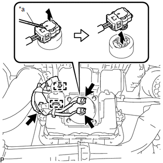
(b) Disconnect the 3 airbag connectors.
NOTICE:
When handling the airbag connector, take care not to damage the airbag wire harness.
(c) Disengage the 2 clamps to remove the instrument panel wire assembly.
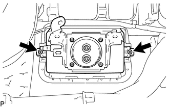
4. REMOVE INSTRUMENT PANEL PASSENGER AIRBAG ASSEMBLY WITHOUT DOOR
|
(a) Remove the 2 screws. |
|
|
(b) Disengage the 3 hooks (A). Text in Illustration
|
|
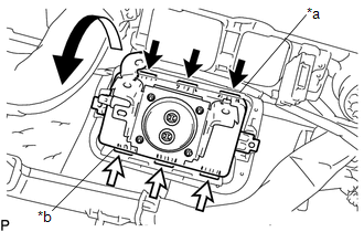
(c) Disengage the 3 hooks (B) to remove the instrument panel passenger airbag assembly without door from the instrument panel.
 On-vehicle Inspection
ON-VEHICLE INSPECTION
PROCEDURE
1. INSPECT INSTRUMENT PANEL PASSENGER AIRBAG ASSEMBLY WITHOUT DOOR (for Vehicle
not Involved in Collision)
(a) Perform a diagnostic system check (See pa ...
 Disposal
DISPOSAL
CAUTION / NOTICE / HINT
CAUTION:
Before performing pre-disposal deployment of any SRS part, review and closely
follow all applicable environmental and hazardous material regulations. Pre ...
Other materials:
Lost Communication With Vehicle Dynamics Control Module (U0122)
DESCRIPTION
This DTC is detected if communication is lost with the skid control ECU (brake
actuator assembly).
DTC No.
Detection Item
DTC Detection Condition
Trouble Area
U0122
Lost Communication with Vehicle Dynamics Contro ...
Brake Booster Pump Motor on Time Abnormally Long (C1252)
DESCRIPTION
The motor relay (semiconductor relay) is built into the master cylinder solenoid
and drives the pump motor based on a signal from the skid control ECU (master cylinder
solenoid).
DTC No.
DTC Detecting Condition
Trouble Areas
C1252
...
Rear seats (Access Cab and Double Cab models)
Access Cab models
The bottom cushion of the rear seats can be raised and lowered.
■ Before raising the bottom cushion
Stow the seat belt buckles.
This prevents the seat belt buckles from falling out when you fold the seatback.
■ Raising the bottom cushion
Raise the bottom cushi ...
