Toyota Tacoma (2015-2018) Service Manual: Installation
INSTALLATION
PROCEDURE
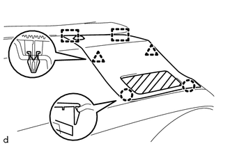
1. INSTALL INSTRUMENT PANEL SUB-ASSEMBLY
(a) Engage the 5 guides to install the instrument panel sub-assembly.
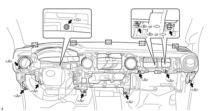
(b) Engage the clamps and connect the connectors.
(c) Install the nut <G>.
(d) Install the 8 bolts <A>.
(e) Install the 2 bolts <B> or 2 bolts <C>.
Torque:
20 N·m {204 kgf·cm, 15 ft·lbf}
2. INSTALL INSTRUMENT PANEL LOWER CENTER FINISH PANEL
(a) Connect the connectors.
|
(b) Engage the 7 clips to install the instrument panel lower center finish panel. |
|
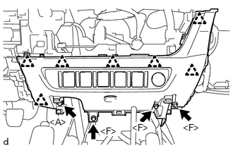
(c) Install the 3 screws <F>.
(d) Install the bolt <A>.
3. INSTALL NO. 2 INSTRUMENT PANEL GARNISH SUB-ASSEMBLY
(a) Engage the 8 clips to install the No. 2 instrument panel garnish sub-assembly.
(b) Install the screw <F>.
4. INSTALL INSTRUMENT LOWER PANEL ASSEMBLY
(a) Engage the 4 clips to install the instrument lower panel assembly.
(b) Install the 5 screws <F>.
5. INSTALL LOWER NO. 2 INSTRUMENT PANEL AIRBAG ASSEMBLY
Click here .gif)
6. INSTALL GLOVE COMPARTMENT PLATE
(a) Engage the 5 clips to install the glove compartment plate.
7. INSTALL INSTRUMENT SIDE PANEL RH
(a) Engage the 3 guides, 3 clips and 4 claws to install the instrument side panel RH.
8. INSTALL AIR CONDITIONING CONTROL ASSEMBLY (for Automatic Air Conditioning System)
Click here
9. INSTALL AIR CONDITIONING CONTROL ASSEMBLY (for Manual Air Conditioning System)
Click here
10. INSTALL INSTRUMENT PANEL LOWER FINISH PANEL SUB-ASSEMBLY
(a) Connect the connectors.
|
(b) Engage the 4 claws and 11 clips to install the instrument panel lower finish panel sub-assembly. |
|
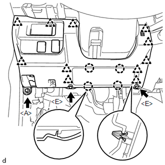
(c) Install the 2 screws <E>.
(d) Install the bolt <A>.
11. CONNECT HOOD LOCK CONTROL LEVER SUB-ASSEMBLY
(a) Engage the claw and 3 guides to connect the hood lock control lever sub-assembly.
12. INSTALL COMBINATION METER ASSEMBLY
Click here
13. INSTALL NAVIGATION RECEIVER ASSEMBLY (w/ Navigation System)
Click here
14. INSTALL RADIO AND DISPLAY RECEIVER ASSEMBLY (w/o Navigation System)
Click here
15. INSTALL INSTRUMENT CLUSTER FINISH PANEL ASSEMBLY
(a) Engage the 8 guides, 3 claws and 8 clips to install the instrument cluster finish panel assembly.
16. INSTALL INSTRUMENT CLUSTER CENTER FINISH PANEL SUB-ASSEMBLY
(a) Engage the 10 clips to install the instrument cluster center finish panel sub-assembly.
17. INSTALL FRONT NO. 2 SPEAKER ASSEMBLY LH
Click here
18. INSTALL FRONT NO. 2 SPEAKER ASSEMBLY RH
Click here
19. INSTALL NO. 1 INSTRUMENT PANEL SPEAKER PANEL SUB-ASSEMBLY
|
(a) Engage the 2 guides, 3 clips and 2 claws to install the No. 1 instrument panel speaker panel sub-assembly. |
|
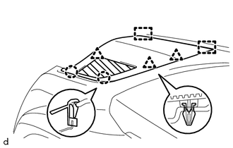
20. INSTALL NO. 2 INSTRUMENT PANEL SPEAKER PANEL SUB-ASSEMBLY
(a) Connect the connector.
|
(b) Engage the 2 guides, 2 clips and 2 claws to install the No. 2 instrument panel speaker panel sub-assembly. |
|
21. INSTALL FRONT PILLAR GARNISH LH
Click here
22. INSTALL FRONT PILLAR GARNISH RH
Click here
23. INSTALL ASSIST GRIP SUB-ASSEMBLY
Click here
24. CONNECT FRONT DOOR OPENING TRIM WEATHERSTRIP LH
(a) Connect the front door opening trim weatherstrip LH.
25. CONNECT FRONT DOOR OPENING TRIM WEATHERSTRIP RH
HINT:
Use the same procedure as for the LH side.
26. INSTALL COWL SIDE TRIM BOARD LH
Click here
27. INSTALL COWL SIDE TRIM BOARD RH
HINT:
Use the same procedure as for the LH side.
28. INSTALL FRONT DOOR SCUFF PLATE LH (for Access Cab)
Click here
29. INSTALL FRONT DOOR SCUFF PLATE RH (for Access Cab)
HINT:
Use the same procedure as for the LH side.
30. INSTALL FRONT DOOR SCUFF PLATE LH (for Double Cab)
Click here
31. INSTALL FRONT DOOR SCUFF PLATE RH (for Double Cab)
HINT:
Use the same procedure as for the LH side.
32. INSTALL FRONT CONSOLE BOX
Click here
33. CONNECT CABLE TO NEGATIVE BATTERY TERMINAL
Torque:
5.4 N·m {55 kgf·cm, 48 in·lbf}
NOTICE:
When disconnecting the cable, some systems need to be initialized after the cable is reconnected.
Click here
34. INSPECT SRS WARNING LIGHT
Click here
 Removal
REMOVAL
PROCEDURE
1. TABLE OF BOLT, SCREW AND NUT
HINT:
All bolts, screws and nuts relevant to installing and removing the instrument
panel are shown along with their alphabetic codes in the tab ...
 Reassembly
REASSEMBLY
PROCEDURE
1. INSTALL INSTRUMENT PANEL CUSHION
(a) Install a new instrument panel cushion as shown in the illustration.
Text in Illustration
*a
...
Other materials:
Sound of Portable Player cannot be Heard from Speakers or Sound is Low
PROCEDURE
1.
CHECK PORTABLE PLAYER SETTINGS
(a) Check the portable player settings.
(1) Check that the volume is not set to "0".
(2) Check that the mute is off.
(b) Check that the sound of the portable player can be heard from the speakers.
OK:
Sound ...
Removal
REMOVAL
PROCEDURE
1. REMOVE STEERING PAD
(See page
)
2. REMOVE STEERING WHEEL ASSEMBLY
3. REMOVE LOWER STEERING COLUMN COVER
4. REMOVE UPPER STEERING COLUMN COVER
5. REMOVE SPIRAL CABLE SUB-ASSEMBLY WITH SENSOR
(a) Slide the slider and disconnect the airbag connect ...
Installation
INSTALLATION
PROCEDURE
1. TEMPORARILY TIGHTEN FRONT SUSPENSION LOWER ARM
(a) Align the matchmarks on the camber adjust cam No. 2 and toe adjust cam. Temporarily
tighten the bolt and the nut.
(b) Install the front lower ball joint attachment, a new nut and a new cotter
pin.
Torque:
140 N ...
