Toyota Tacoma (2015-2018) Service Manual: Front Axle Hub Bolt
Installation
INSTALLATION
PROCEDURE
1. INSTALL FRONT AXLE HUB BOLT
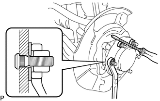
(a) Install a new hub bolt through the axle hub.
(b) Install the washer plate, as shown in the illustration, through the hub bolt, and install the hub bolt by tightening the hub nut.
2. INSTALL FRONT DISC
3. INSTALL FRONT DISC BRAKE CALIPER ASSEMBLY
Click here .gif)
4. INSTALL FRONT WHEEL
Torque:
113 N·m {1152 kgf·cm, 83 ft·lbf}
5. CONNECT CABLE TO NEGATIVE BATTERY TERMINAL
Torque:
5.4 N·m {55 kgf·cm, 48 in·lbf}
NOTICE:
When disconnecting the cable, some systems need to be initialized after the cable is reconnected.
Click here
6. FILL RESERVOIR WITH BRAKE FLUID (for Hydraulic Brake Booster)
Click here
7. FILL RESERVOIR WITH BRAKE FLUID (for Vacuum Brake Booster)
Click here
8. BLEED MASTER CYLINDER (for Vacuum Brake Booster)
Click here
9. BLEED BRAKE LINE (for Hydraulic Brake Booster)
Click here
10. BLEED BRAKE LINE (for Vacuum Brake Booster)
Click here
11. INSPECT FLUID LEVEL IN RESERVOIR (for Hydraulic Brake Booster)
Click here
12. INSPECT FLUID LEVEL IN RESERVOIR (for Vacuum Brake Booster)
Click here
13. INSPECT FOR BRAKE FLUID LEAK
Removal
REMOVAL
PROCEDURE
1. PRECAUTION
NOTICE:
After turning the ignition switch off, waiting time may be required before disconnecting the cable from the negative (-) battery terminal.
Therefore, make sure to read the disconnecting the cable from the negative (-) battery terminal notices before proceeding with work.
Click here .gif)
2. DISCONNECT CABLE FROM NEGATIVE BATTERY TERMINAL
NOTICE:
When disconnecting the cable, some systems need to be initialized after the cable is reconnected.
Click here
3. REMOVE FRONT WHEEL
4. DRAIN BRAKE FLUID
NOTICE:
Immediately wash off any brake fluid that comes into contact with painted surfaces.
5. REMOVE FRONT DISC BRAKE CALIPER ASSEMBLY
Click here
6. REMOVE FRONT DISC
7. REMOVE FRONT AXLE HUB BOLT
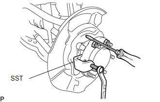
(a) Using SST and a screwdriver, remove the hub bolt.
SST: 09611-12010
 Installation
INSTALLATION
PROCEDURE
1. INSTALL FRONT AXLE HUB
2. INSTALL FRONT SUSPENSION UPPER ARM
(a) Install a new nut and clip.
Torque:
110 N·m {1122 kgf·cm, 81 ft·lbf}
3. INSTALL FRONT SUSPENSION ...
 Rear Axle Hub Bolt
Installation
INSTALLATION
PROCEDURE
1. INSTALL REAR AXLE HUB BOLT
(a) Install a new hub bolt through the axle hub.
(b) Install the washer plate, as shown in the illustration, through the hub ...
Other materials:
Data List / Active Test
DATA LIST / ACTIVE TEST
1. DATA LIST
HINT:
Using the Techstream to read the Data List allows the values or states of switches,
sensors, actuators and other items to be read without removing any parts. This non-intrusive
inspection can be very useful because intermittent conditions or signals ...
Removal
REMOVAL
PROCEDURE
1. DRAIN DIFFERENTIAL OIL
2. REMOVE PROPELLER WITH CENTER BEARING SHAFT ASSEMBLY (for 2WD)
3. REMOVE PROPELLER WITH CENTER BEARING SHAFT ASSEMBLY (for 4WD)
4. REMOVE REAR DRIVE PINION NUT
(a) Using SST and a hammer, unstake the nut.
SST: 09930-00010
(b) for BD20:
...
How To Proceed With Troubleshooting
CAUTION / NOTICE / HINT
HINT:
Use this procedure to troubleshoot the engine immobiliser system.
*: Use the Techstream.
PROCEDURE
1.
VEHICLE BROUGHT TO WORKSHOP
NEXT
2 ...
