Toyota Tacoma (2015-2018) Service Manual: Disassembly
DISASSEMBLY
PROCEDURE
1. REMOVE TAIL GATE PROTECTOR
(See page .gif) )
)
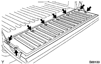
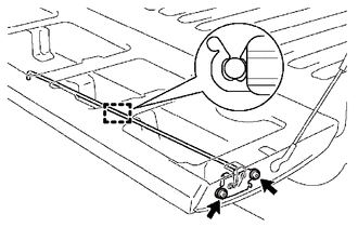
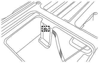
2. REMOVE TAIL GATE SERVICE HOLE COVER
|
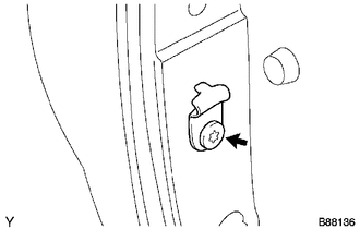
(a) Using a T30 "TORX" socket wrench, remove the 8 screws and tail gate service hole cover. |
|
3. REMOVE REAR TELEVISION CAMERA ASSEMBLY
4. REMOVE TAIL GATE LOCK ASSEMBLY LH
|
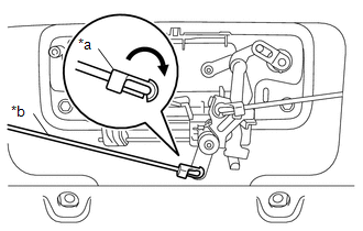
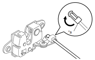
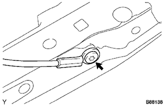
(a) Disconnect the snap and tail gate lock control link from the tail gate handle assembly as shown in the illustration. Text in Illustration
|
|
|
(b) Disengage the clamp. |
|
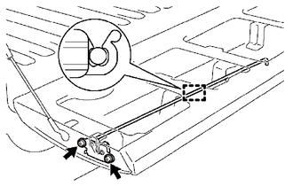
(c) Using a T40 "TORX" socket wrench, remove the 2 bolts and tail gate lock assembly LH.
5. REMOVE TAIL GATE LOCK ASSEMBLY RH
|
(a) Disconnect the snap and tail gate lock control link from the tail gate handle assembly as shown in the illustration. Text in Illustration
|
|
|
(b) Disengage the clamp. |
|
(c) Using a T40 "TORX" socket wrench, remove the 2 bolts and tail gate lock assembly RH.
6. REMOVE TAIL GATE LOCK CONTROL LINK
|
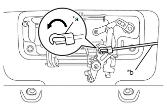
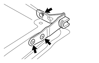
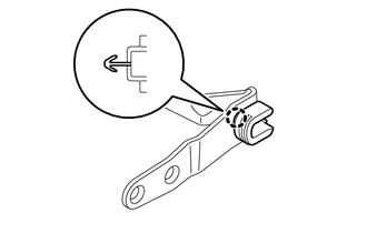
(a) Disconnect the snap to remove the tail gate lock control link from the tail gate lock assembly LH as shown in the illustration. Text in Illustration
HINT: Use the same procedure for the LH side and RH side. |
|
7. REMOVE TAIL GATE HANDLE ASSEMBLY
|
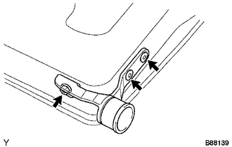
(a) Remove the 2 bolts. |
|
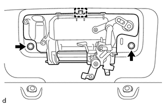
(b) Disengage the guide to remove the tail gate handle assembly.
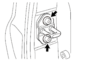
8. REMOVE TAIL GATE LOCK STRIKER
|
(a) Using a T40 "TORX" socket wrench, remove the 2 bolts and tail gate lock striker. HINT: Use the same procedure for the LH side and RH side. |
|
9. REMOVE TAIL GATE
|
(a) Disengage the clamp. |
|
|
(b) Disengage the clamp. |
|
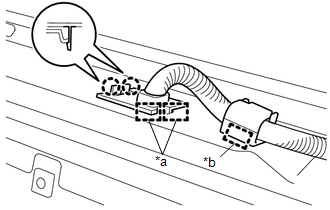
(c) Disengage the 2 claws and 2 guides to disconnect the wire harness from the tail gate.
Text in Illustration|
*a |
Guide |
|
*b |
Clamp |
|
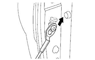
(d) Disengage the tail gate stay from the tail gate stay stopper as shown in the illustration. HINT: Use the same procedure for the LH side and RH side. |
|
|
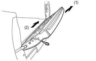
(e) Remove the tail gate from the vehicle in the order shown in the illustration. NOTICE: Be careful not to drop the tail gate. HINT: Remove the tail gate from the vehicle by lifting up the right side and sliding it slightly to the right. |
|
10. REMOVE TAIL GATE STAY STOPPER
|
(a) Using a T40 "TORX" socket wrench, remove the tail gate stay shaft and tail gate stopper. HINT: Use the same procedure for the LH side and RH side. |
|
11. REMOVE TAIL GATE STAY ASSEMBLY
|
(a) Using a T40 "TORX" socket wrench, remove the tail gate stay shaft, washer and tail gate stay assembly. HINT: Use the same procedure for the LH side and RH side. |
|
12. REMOVE TAIL GATE HINGE ASSEMBLY LH
|
(a) Using a T40 "TORX" socket wrench, remove the bolt, 2 screws and tail gate hinge assembly LH. |
|
13. REMOVE TAIL GATE HINGE ASSEMBLY RH
|
(a) Using a T40 "TORX" socket wrench, remove the bolt, 2 screws and tail gate hinge assembly RH. |
|
14. REMOVE SIDE GATE SUPPORT FEMALE HINGE RH
|
(a) Disengage the claw to remove the side gate support female hinge RH. |
|
15. REMOVE NO. 2 REAR BODY NAME PLATE (for 4WD)
16. REMOVE NO. 3 REAR BODY NAME PLATE (for 2GR-FKS)
 Components
COMPONENTS
ILLUSTRATION
ILLUSTRATION
ILLUSTRATION
...
 Reassembly
REASSEMBLY
PROCEDURE
1. INSTALL NO. 3 REAR BODY NAME PLATE (for 2GR-FKS)
2. INSTALL NO. 2 REAR BODY NAME PLATE (for 4WD)
3. INSTALL SIDE GATE SUPPORT FEMALE HINGE RH
(a) Engage ...
Other materials:
Cruise Control Switch Circuit
DESCRIPTION
This circuit sends signals to the ECM depending on the cruise control main switch
condition.
The battery supplies the positive (+) battery voltage to the cruise control main
switch. Then terminal CCS of the ECM receives the voltage as the signal according
to the switch condition. ...
Transfer System
Precaution
PRECAUTION
Before disassembly, clean the transfer assembly and remove any deposited
sand and mud to prevent it from entering the transfer during disassembly
and assembly.
When removing any light alloy parts such as the transfer covers, do
not pry them off with a ...
Front Airbag Sensor RH Circuit Malfunction (B1610/13)
DESCRIPTION
The front airbag sensor RH consists of parts such as the diagnostic circuit and
the frontal detection sensor.
When the airbag sensor assembly receives signals from the frontal deceleration
sensor, it determines whether or not the SRS should be activated.
DTC B1610/13 is set when a ...
