Toyota Tacoma (2015-2018) Service Manual: Light Sensor Circuit Malfunction (B1244)
DESCRIPTION
This DTC is output when a failure of the automatic light control sensor circuit is detected.
|
DTC Code |
DTC Detection Condition |
Trouble Area |
|---|---|---|
|
B1244 |
When either condition below is met:
|
|
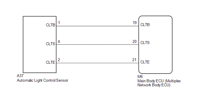
WIRING DIAGRAM
CAUTION / NOTICE / HINT
NOTICE:
If the main body ECU (multiplex network body ECU) is replaced, refer to Registration
(See page .gif) ).*1
).*1
- *1: w/ Smart Key System
PROCEDURE
|
1. |
CHECK FOR DTC |
(a) Clear the DTC (See page ).
(b) Recheck for DTC (See page ).
OK:
DTC B1244 is not output.
| OK | .gif) |
USE SIMULATION METHOD TO CHECK |
|
.gif)
|
2. |
READ VALUE USING TECHSTREAM (LIGHT SENSOR ILLUMINANCE) |
(a) Connect the Techstream to the DLC3.
(b) Turn the ignition switch to ON.
(c) Turn the Techstream on.
(d) Enter the following menus: Body Electrical / Main Body / Data List.
(e) According to the display on the Techstream, read the Data List.
Main Body|
Tester Display |
Measurement Item/Range |
Normal Condition |
Diagnostic Note |
|---|---|---|---|
|
Light Sensor Illuminance |
Light control sensor illuminance / 0 to 8191 lx |
Value is output according to ambient light level |
- |
OK:
Output illuminance is as shown in table above.
| OK | |
REPLACE MAIN BODY ECU (MULTIPLEX NETWORK BODY ECU) |
|
|
3. |
CHECK MAIN BODY ECU (MULTIPLEX NETWORK BODY ECU) (LIGHT CONTROL SENSOR VOLTAGE) |
|
(a) Disconnect the ECU connector. |
|
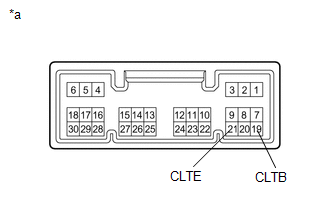
(b) Measure the voltage according to the value(s) in the table below.
Standard voltage:
|
Tester Connection |
Switch Condition |
Specified Condition |
|---|---|---|
|
19 (CLTB) - 21 (CLTE) |
Ignition switch ON |
11 to 14 V |
|
Ignition switch OFF |
Below 1 V |
|
*a |
Component without harness connected (Main Body ECU (Multiplex Network Body ECU)) |
| NG | |
REPLACE MAIN BODY ECU (MULTIPLEX NETWORK BODY ECU) |
|
|
4. |
CHECK HARNESS AND CONNECTOR (MAIN BODY ECU (MULTIPLEX NETWORK BODY ECU) - AUTOMATIC LIGHT CONTROL SENSOR) |
(a) Disconnect the M6 main body ECU (multiplex network body ECU) connector.
(b) Disconnect the A37 automatic light control sensor connector.
(c) Measure the resistance according to the value(s) in the table below.
Standard resistance:
|
Tester Connection |
Condition |
Specified Condition |
|---|---|---|
|
M6-19 (CLTB) - A37-1 (CLTB) |
Always |
Below 1 Ω |
|
M6-20 (CLTS) - A37-4 (CLTS) |
||
|
M6-21 (CLTE) - A37-2 (CLTE) |
||
|
M6-19 (CLTB) - Body ground |
Always |
10 kΩ or higher |
|
M6-20 (CLTS) - Body ground |
||
|
M6-21 (CLTE) - Body ground |
| OK | |
REPLACE AUTOMATIC LIGHT CONTROL SENSOR |
| NG | |
REPAIR OR REPLACE HARNESS OR CONNECTOR |
 Terminals Of Ecu
TERMINALS OF ECU
1. CHECK MAIN BODY ECU (MULTIPLEX NETWORK BODY ECU)
Text in Illustration
*1
Main Body ECU (Multiplex Network Body ECU)
-
-
(a ...
 Data List / Active Test
DATA LIST / ACTIVE TEST
1. DATA LIST
HINT:
Using the Techstream to read the Data List allows values or states of switches,
sensors, actuators and other items to be read without removing any parts ...
Other materials:
System Description
SYSTEM DESCRIPTION
1. FUNCTION OF MAIN COMPONENTS
Component
Function
Vertical mirror motor
Moves the mirror surface vertically in accordance with the vertical mirror
motor outer mirror switch assembly operation.
Horizontal mirr ...
Installation
INSTALLATION
CAUTION / NOTICE / HINT
NOTICE:
If the millimeter wave radar sensor assembly has been struck or dropped, replace
the millimeter wave radar sensor assembly with a new one.
PROCEDURE
1. INSTALL MILLIMETER WAVE RADAR SENSOR ASSEMBLY
(a) for Type A:
(1) Engage the 2 gu ...
Installation
INSTALLATION
PROCEDURE
1. INSPECT FRONT PROPELLER SHAFT ASSEMBLY (with Grease Fitting)
HINT:
When replacing the spider bearing, make sure that the grease fitting assembly
hole is facing in the direction shown in the illustration.
Text in Illustration
*1
No. 1 Grease Fi ...
