Toyota Tacoma (2015-2018) Service Manual: Rear Seat Inner Belt Assembly(for Access Cab)
Components
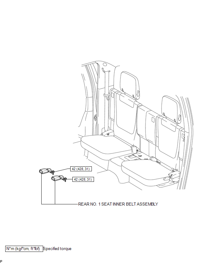
COMPONENTS
ILLUSTRATION
Removal
REMOVAL
PROCEDURE
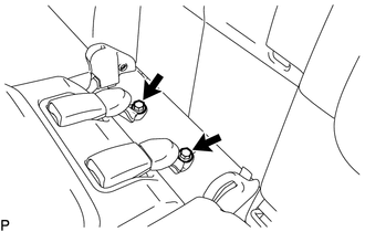
1. REMOVE REAR NO. 1 SEAT INNER BELT ASSEMBLY
(a) Open the 2 anchor covers.
|
(b) Loosen the 2 bolts to remove the 2 rear No. 1 seat inner belt assemblies. |
|
Installation
INSTALLATION
PROCEDURE
1. INSTALL REAR NO. 1 SEAT INNER BELT ASSEMBLY
(a) Tighten the 2 bolts to install the 2 rear No. 1 seat inner belt assemblies.
Torque:
42 N·m {428 kgf·cm, 31 ft·lbf}
(b) Check that the floor anchor rotates smoothly.
(c) Close the 2 anchor covers.
 Rear Center Seat Outer Belt Assembly(for Double Cab)
Components
COMPONENTS
ILLUSTRATION
Removal
REMOVAL
PROCEDURE
1. REMOVE REAR SEATBACK HINGE COVER
2. REMOVE REAR SEATBACK BOARD SUB-ASSEMBLY
3. REMOVE SEAT BELT ANCHOR COVER CAP
...
 Rear Seat Inner Belt Assembly(for Double Cab)
Installation
INSTALLATION
PROCEDURE
1. INSTALL REAR SEAT INNER BELT ASSEMBLY
(a) for LH Side:
(1) Install the rear seat inner belt assembly with the bolt.
Text in Illustration
...
Other materials:
Installation
INSTALLATION
CAUTION / NOTICE / HINT
NOTICE:
If the millimeter wave radar sensor assembly has been struck or dropped, replace
the millimeter wave radar sensor assembly with a new one.
PROCEDURE
1. INSTALL MILLIMETER WAVE RADAR SENSOR ASSEMBLY
(a) for Type A:
(1) Engage the 2 gu ...
Parts Location
PARTS LOCATION
ILLUSTRATION
ILLUSTRATION
ILLUSTRATION
ILLUSTRATION
...
Diagnostic Trouble Code Chart
DIAGNOSTIC TROUBLE CODE CHART
Steering Lock System
DTC Code
Detection Item
See page
B2781
Open / Short in Steering Lock ECU
B2782
Power Source Control ECU Malfunction
...
