Toyota Tacoma (2015-2018) Service Manual: Main Switch Power Source Circuit
DESCRIPTION
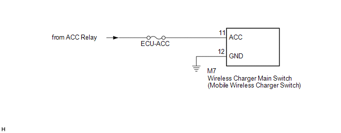
This circuit supplies power to the wireless charger main switch (mobile wireless charger switch) and illuminates the switch indicator light when the wireless charger main switch (mobile wireless charger switch) is turned on.
WIRING DIAGRAM
CAUTION / NOTICE / HINT
NOTICE:
Inspect the fuses for circuits related to this system before performing the following inspection procedure.
PROCEDURE
|
1. |
CHECK HARNESS AND CONNECTOR (WIRELESS CHARGER MAIN SWITCH (MOBILE WIRELESS CHARGER SWITCH) POWER SOURCE) |
(a) Disconnect the M7 wireless charger main switch (mobile wireless charger switch) connector.
(b) Measure the resistance according to the value(s) in the table below.
Standard Resistance:
|
Tester Connection |
Condition |
Specified Condition |
|---|---|---|
|
M7-12 (GND) - Body ground |
Always |
Below 1 Ω |
|
M7-11 (ACC) - Body ground |
Always |
10 kΩ or higher |
(c) Measure the voltage according to the value(s) in the table below.
Standard Voltage:
|
Tester Connection |
Switch Condition |
Specified Condition |
|---|---|---|
|
M7-11 (ACC) - M7-12 (GND) |
Ignition switch ACC |
11 to 14 V |
| OK | .gif) |
PROCEED TO NEXT SUSPECTED AREA SHOWN IN PROBLEM SYMPTOMS TABLE |
| NG | |
REPAIR OR REPLACE HARNESS OR CONNECTOR |
 Problem Symptoms Table
PROBLEM SYMPTOMS TABLE
HINT:
Use the table below to help determine the cause of problem symptoms.
If multiple suspected areas are listed, the potential causes of the symptoms
are lis ...
 Terminals Of Ecu
TERMINALS OF ECU
1. MOBILE WIRELESS CHARGER CRADLE ASSEMBLY
Tester Connection
Wiring Color
Terminal Description
Condition
Specified Condition ...
Other materials:
Rear Speed Sensor RH Output Malfunction (C1415,C1416)
DESCRIPTION
Refer to DTCs C1403 and C1404 (See page ).
DTC No.
Detection Item
DTC Detection Condition
Trouble Area
C1415
Rear Speed Sensor RH Output Malfunction
Any of the following is detected:
An op ...
Air Inlet Control Servo Motor
Inspection
INSPECTION
PROCEDURE
1. INSPECT AIR INLET CONTROL SERVO MOTOR
(a) Inspect the servo motor operation.
(1) Connect the positive (+) lead from the battery to terminal 1 (FRS)
and negative (-) lead to terminals 2 (REC), then check that the shaft rotates
clockwise s ...
Dtc Check / Clear
DTC CHECK / CLEAR
NOTICE:
When the diagnosis system is changed from normal mode to check mode or vice versa,
all DTCs and freeze frame data recorded in normal mode are cleared. Before changing
modes, always check and make a note of DTCs and freeze frame data.
HINT:
DTCs which are sto ...
