Toyota Tacoma (2015-2018) Service Manual: Rear Door(for Access Cab)
Adjustment
ADJUSTMENT
CAUTION / NOTICE / HINT
HINT:
- Use the same procedures for both the LH and RH sides.
- The procedure described below is for the LH side.
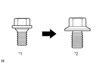
- Centering bolts are used to mount the door hinge to the vehicle body
and door. The door cannot be adjusted with the centering bolts on. Substitute
the centering bolts for standard bolts when making adjustments.
 Text in Illustration
*1
Centering Bolt
*2
Standard Bolt
- A bolt without a torque specification is shown in the standard bolt
chart (See page
.gif) ).
).
PROCEDURE
1. INSPECT REAR DOOR PANEL SUB-ASSEMBLY
(a) Check that the clearance measurements of areas "A" through "F" are within each standard range.
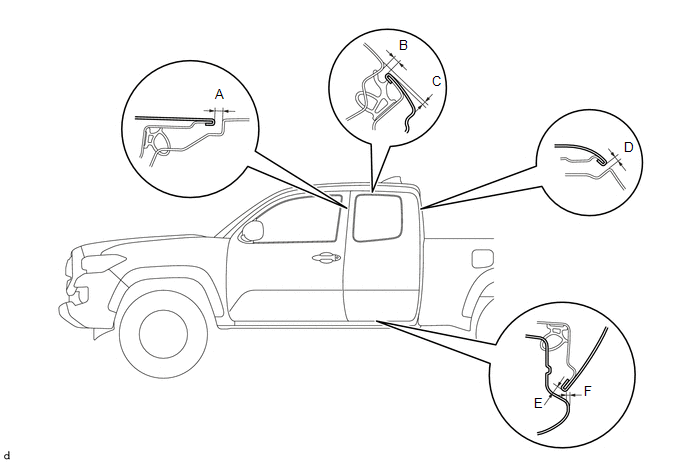
Standard Clearance:
|
Area |
Measurement |
Area |
Measurement |
|---|---|---|---|
|
A |
4.5 to 7.5 mm (0.177 to 0.295 in.) |
B |
3.8 to 6.8 mm (0.150 to 0.268 in.) |
|
C |
0.3 to 3.3 mm (0.012 to 0.130 in.) |
D |
4.6 to 7.6 mm (0.181 to 0.299 in.) |
|
E |
3.5 to 6.5 mm (0.138 to 0.256 in.) |
F |
0.5 to 3.5 mm (0.020 to 0.138 in.) |
2. ADJUST REAR DOOR PANEL SUB-ASSEMBLY
|
(a) Adjust the door horizontally and vertically by loosening the 4 body side hinge bolts. |
|
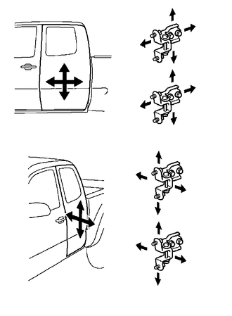
(b) Tighten the 4 body side hinge bolts after the adjustment.
Torque:
26 N·m {265 kgf·cm, 19 ft·lbf}
NOTICE:
Adjust the door fitting after the bolts were replaced with new ones.
(c) Adjust the door horizontally and vertically by loosening the 4 door side hinge bolts.
(d) Tighten the 4 door side hinge bolts after the adjustment.
Torque:
26 N·m {265 kgf·cm, 19 ft·lbf}
NOTICE:
Adjust the door fitting after the bolts were replaced with new ones.
|
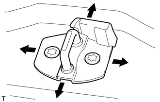
(e) Using a T40 "TORX" socket wrench, slightly loosen the 2 striker mounting screws. |
|
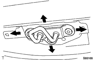
(f) Using a brass bar and a hammer, hit the striker to adjust its position.
(g) Using a T40 "TORX" socket wrench, tighten the 2 striker mounting screws after adjustment.
Torque:
23 N·m {235 kgf·cm, 17 ft·lbf}
|
(h) Using a T40 "TORX" socket wrench, slightly loosen the 2 striker mounting screws. |
|
(i) Using a brass bar and a hammer, hit the striker to adjust its position.
(j) Using a T40 "TORX" socket wrench, tighten the 2 striker mounting screws after adjustment.
Torque:
23 N·m {235 kgf·cm, 17 ft·lbf}
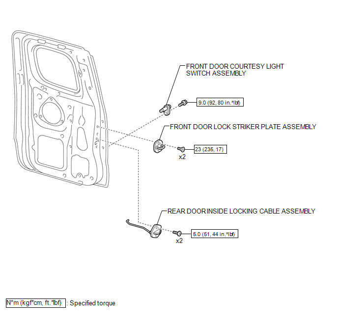
Components
COMPONENTS
ILLUSTRATION
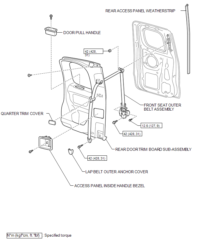
ILLUSTRATION
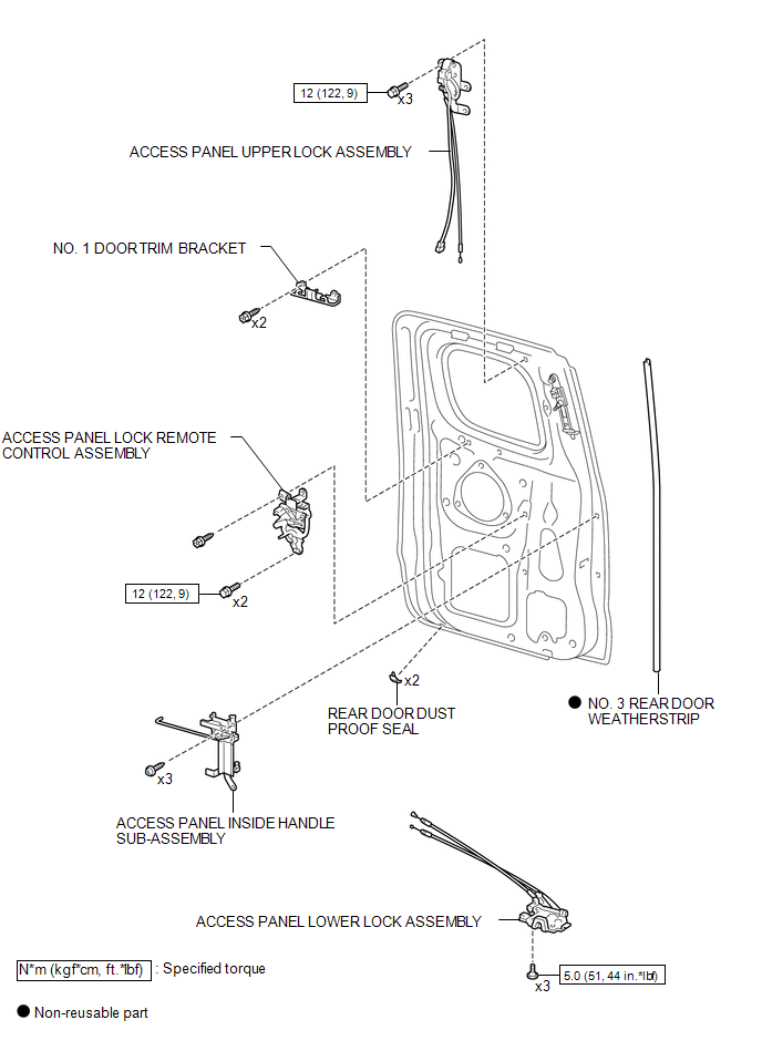
ILLUSTRATION
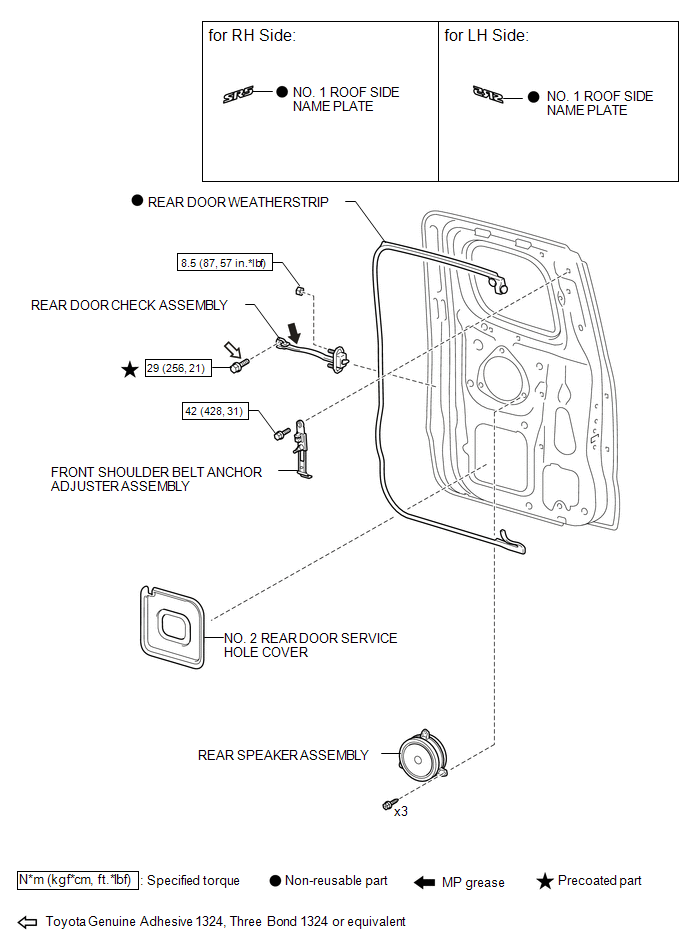
ILLUSTRATION
 Reassembly
REASSEMBLY
CAUTION / NOTICE / HINT
NOTICE:
When installing the hood bulge protector, heat the hood bulge surface
using the infrared light.
Do not heat the hood bulge excessively.
...
 Rear Door(for Double Cab)
Components
COMPONENTS
ILLUSTRATION
ILLUSTRATION
ILLUSTRATION
ILLUSTRATION
ILLUSTRATION
Adjustment
ADJUSTMENT
CAUTION / NOTICE / HINT
HINT:
Use the same procedures for ...
Other materials:
Terminals Of Ecu
TERMINALS OF ECU
1. CHECK CERTIFICATION ECU (SMART KEY ECU ASSEMBLY)
(a) Disconnect the C27 and C29 certification ECU (smart key ECU assembly) connectors.
(b) Measure the voltage and resistance according to the value(s) in the table
below.
HINT:
Measure the values on the wire harness side w ...
Installation
INSTALLATION
CAUTION / NOTICE / HINT
HINT:
Use the same procedure for both the RH and LH sides.
The procedure described below is for the LH side.
PROCEDURE
1. INSTALL CURTAIN SHIELD AIRBAG ASSEMBLY
(a) Insert the 5 hooks, install 6 new bolts, 2 new clips with pins and 2 new
...
On-vehicle Inspection
ON-VEHICLE INSPECTION
PROCEDURE
1. CHECK FUEL PUMP ASSEMBLY OPERATION
(a) Check fuel pressure.
(1) Connect the Techstream to the DLC3.
(2) Start the engine.
(3) Turn the Techstream on.
(4) Enter the following menus: Powertrain / Engine / Active Test / Control the
Target Fuel Pressure.
(5) ...
