Toyota Tacoma (2015-2018) Service Manual: Rear Door(for Double Cab)
Components
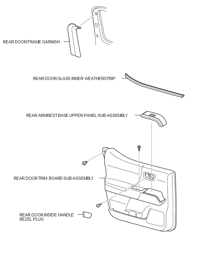
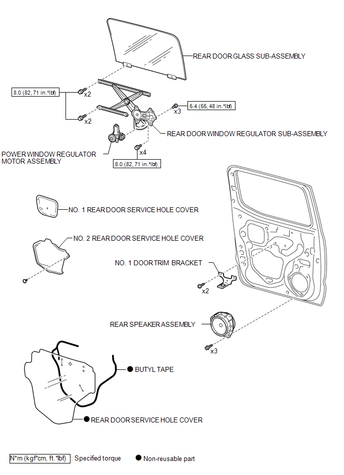
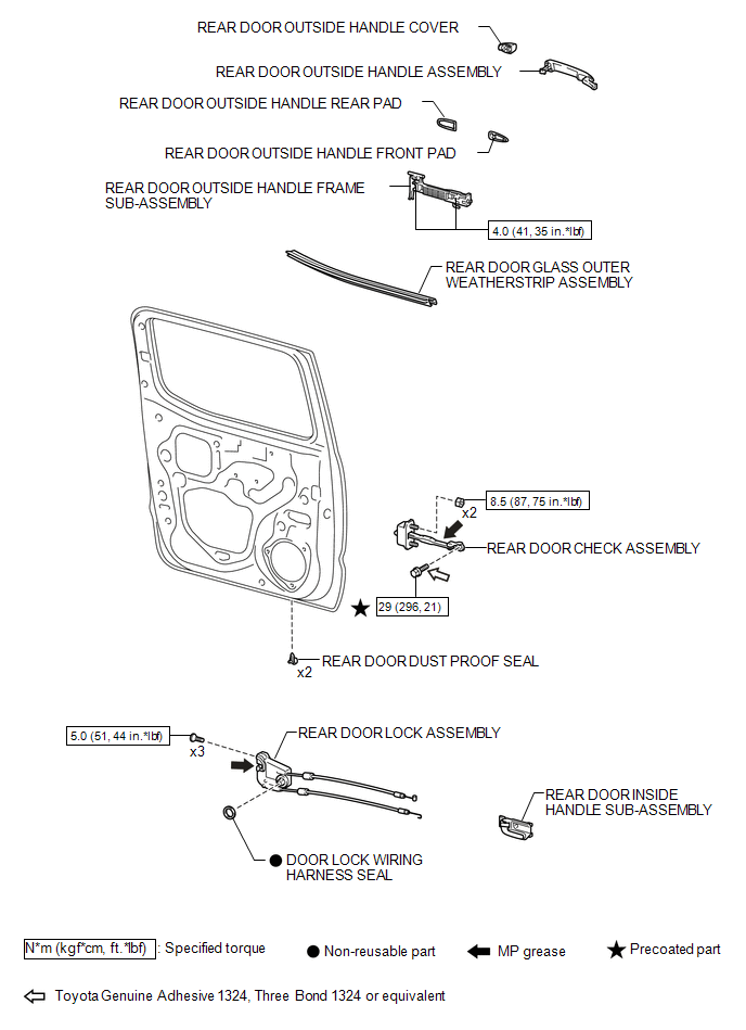
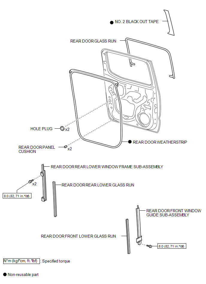
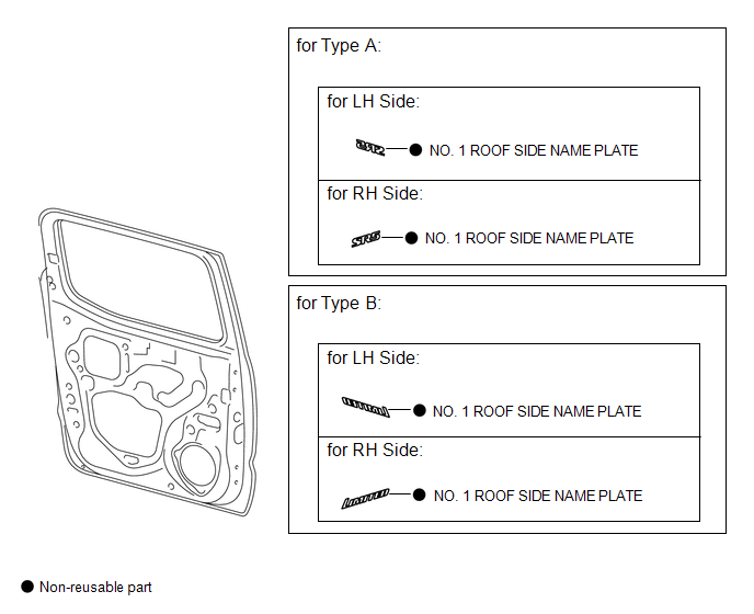
COMPONENTS
ILLUSTRATION
ILLUSTRATION
ILLUSTRATION
ILLUSTRATION
ILLUSTRATION
Adjustment
ADJUSTMENT
CAUTION / NOTICE / HINT
HINT:
- Use the same procedures for both the LH and RH sides.
- The procedure described below is for the LH side.
- Centering bolts are used to mount the door hinge to the vehicle body
and door. The door cannot be adjusted with the centering bolts on. Substitute
the centering bolts for standard bolts when making adjustments.
.png) Text in Illustration
Text in Illustration
*1
Centering Bolt
*2
Standard Bolt
- A bolt without a torque specification is shown in the standard bolt
chart (See page
.gif) ).
).
PROCEDURE
1. INSPECT REAR DOOR PANEL SUB-ASSEMBLY
(a) Check that the clearance measurements of areas "A" through "F" are within each standard range.
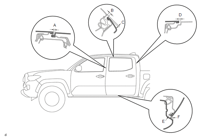 Standard Clearance:
|
Area |
Measurement |
Area |
Measurement |
|---|---|---|---|
|
A |
3.5 to 6.5 mm (0.138 to 0.256 in.) |
B |
3.3 to 6.3 mm (0.130 to 0.248 in.) |
|
C |
0.2 to 3.2 mm (0.008 to 0.126 in.) |
D |
2.9 to 5.9 mm (0.114 to 0.232 in.) |
|
E |
3.4 to 6.4 mm (0.134 to 0.252 in.) |
F |
0.5 to 3.5 mm (0.020 to 0.138 in.) |
2. ADJUST REAR DOOR PANEL SUB-ASSEMBLY
|
(a) Adjust the door horizontally and vertical by loosening the 4 body side hinge bolts. |
|
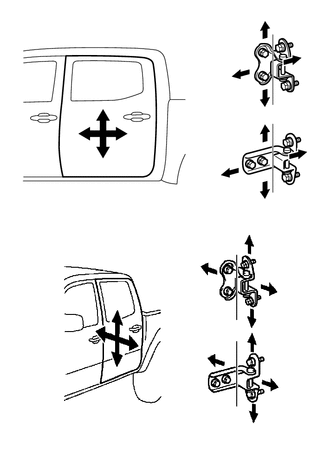
(b) Tighten the 4 body side hinge bolts after the adjustment.
Torque:
26 N·m {265 kgf·cm, 19 ft·lbf}
NOTICE:
Adjust the door fitting after the bolts were replaced with new ones.
(c) Adjust the door horizontally and vertical by loosening the 4 door side hinge bolts.
(d) Tighten the 4 door side hinge bolts after the adjustment.
Torque:
26 N·m {265 kgf·cm, 19 ft·lbf}
NOTICE:
Adjust the door fitting after the bolts were replaced with new ones.
|
(e) Using a T40 "TORX" socket wrench, slightly loosen the 2 striker mounting screws. |
|
.png)
(f) Using a brass bar and a hammer, hit the striker to adjust its position.
(g) Using a T40 "TORX" socket wrench, tighten the 2 striker mounting screws after adjustment.
Torque:
23 N·m {235 kgf·cm, 17 ft·lbf}
 Rear Door(for Access Cab)
Adjustment
ADJUSTMENT
CAUTION / NOTICE / HINT
HINT:
Use the same procedures for both the LH and RH sides.
The procedure described below is for the LH side.
Centering bolts are us ...
 Tail Gate
...
Other materials:
Diagnosis System
DIAGNOSIS SYSTEM
1. DESCRIPTION
The 4 wheel drive control ECU records DTCs when the ECU detects a malfunction
in the ECU itself or in system circuits.
The DTCs can be read through the DLC3 of the vehicle. When the system seems to
be malfunctioning, use the Techstream to check for malfunctions ...
Monitor Drive Pattern
MONITOR DRIVE PATTERN
1. TEST MONITOR DRIVE PATTERN FOR ECT
CAUTION:
Perform this drive pattern on a level surface and strictly observe the posted
speed limits and traffic laws while driving.
HINT:
Performing this drive pattern is one method to simulate the ECM (ECT) malfunction
detection c ...
Rear Shock Absorber
Components
COMPONENTS
ILLUSTRATION
Inspection
INSPECTION
PROCEDURE
1. INSPECT REAR SHOCK ABSORBER
(a) Compress and extend the shock absorber rod and check that there is no abnormal
resistance or abnormal sounds during operation.
If there is any abnormality, replace the shock absorb ...
