Toyota Tacoma (2015-2018) Service Manual: Blower Motor Controller
Components
COMPONENTS
ILLUSTRATION
Removal
REMOVAL
PROCEDURE
1. REMOVE LOWER NO. 2 INSTRUMENT PANEL AIRBAG ASSEMBLY
(See page .gif) )
)
2. REMOVE INSTRUMENT LOWER PANEL ASSEMBLY
3. REMOVE ECM (for 2TR-FE)
(See page )
4. REMOVE ECM (for 2GR-FKS)
(See page )
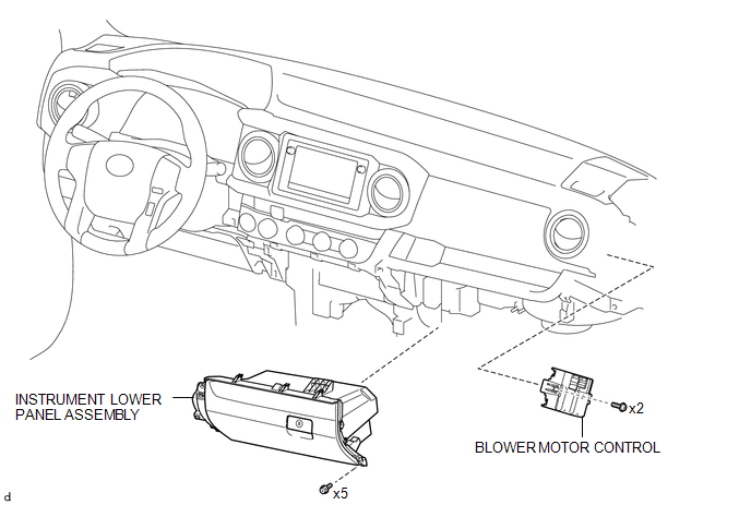
5. REMOVE BLOWER MOTOR CONTROL
|
(a) Disconnect the 2 connectors. |
|
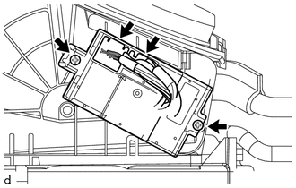
(b) Remove the 2 screws and blower motor control.
Installation
INSTALLATION
PROCEDURE
1. INSTALL BLOWER MOTOR CONTROL
(a) Install the blower motor control with the 2 screws.
(b) Connect the 2 connectors.
2. INSTALL ECM (for 2GR-FKS)
(See page .gif) )
)
3. INSTALL ECM (for 2TR-FE)
(See page )
4. INSTALL INSTRUMENT LOWER PANEL ASSEMBLY
5. INSTALL LOWER NO. 2 INSTRUMENT PANEL AIRBAG ASSEMBLY
(See page )
 Ambient Temperature Sensor
Components
COMPONENTS
ILLUSTRATION
Inspection
INSPECTION
PROCEDURE
1. INSPECT AMBIENT TEMPERATURE SENSOR
(a) Measure the resistance according to the value(s) in the table below ...
 Compressor
...
Other materials:
All Door Entry Lock/Unlock Functions do not Operate, but Wireless Functions
Operate
DESCRIPTION
When the wireless operation can be used to lock and unlock the doors, communication
between the electrical key and TPMS receiver assembly and certification ECU (smart
key ECU assembly) is normal. If the entry lock and unlock functions do not operate,
the entry cancel function may ...
Fail-safe Chart
FAIL-SAFE CHART
HINT:
If any of the following auto cancel conditions are detected while the dynamic
radar cruise control system is controlling vehicle speed, the system clears the
stored vehicle speed and cancels control of vehicle speed by the dynamic radar cruise
control system.
Automatic ...
Noise Occurs or Sound Skips when Portable Player Plays
CAUTION / NOTICE / HINT
HINT:
Perform this check with the portable player volume set at an appropriate
level.
Make sure that there are no obstructions between the portable player
and radio and display receiver assembly that may block signals, and that
the portable player an ...
