Toyota Tacoma (2015-2018) Service Manual: PTC Heater Circuit
DESCRIPTION
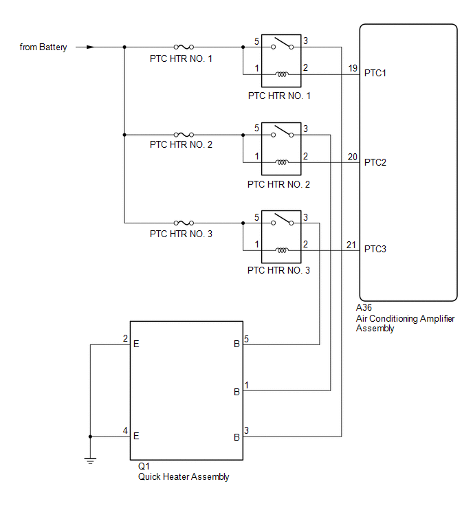
PTC HTR heater relays are closed in accordance with signals from the air conditioning amplifier assembly and power is supplied to the quick heater assembly installed on the radiator heater unit.
WIRING DIAGRAM
CAUTION / NOTICE / HINT
NOTICE:
Inspect the fuses for circuits related to this system before performing the following inspection procedure.
PROCEDURE
|
1. |
PERFORM ACTIVE TEST USING TECHSTREAM |
(a) Connect the Techstream to the DLC3.
(b) Turn the ignition switch to ON.
(c) Turn the Techstream on.
(d) Enter the following menus: Body Electrical / Air Conditioner / Active Test.
(e) Check the operation by referring to the table below.
Air Conditioner|
Tester Display |
Test Part |
Control Range |
Diagnostic Note |
|---|---|---|---|
|
Heater Active Level |
Quick heater assembly |
Min.: 0, Max.: 3 |
- |
OK:
Heater Active Level changes normally.
| NG | .gif) |
PROCEED TO NEXT SUSPECTED AREA SHOWN IN PROBLEM SYMPTOMS TABLE |
|
.gif)
|
2. |
INSPECT PTC HTR RELAY |
(a) Remove the PTC HTR relays.
(b) Inspect the PTC HTR relays (See page .gif) ).
).
| NG | |
REPLACE PTC HTR RELAY |
|
|
3. |
CHECK HARNESS AND CONNECTOR (PTC HTR RELAY - POWER SOURCE CIRCUIT) |
(a) Remove the PTC HTR relays.
(b) Measure the voltage according to the value(s) in the table below.
Standard Voltage:
PTC HTR NO. 1|
Tester Connection |
Condition |
Specified Condition |
|---|---|---|
|
PTC HTR NO. 1-1 - Body ground |
Always |
11 to 14 V |
|
PTC HTR NO. 1-5 - Body ground |
Always |
11 to 14 V |
|
Tester Connection |
Condition |
Specified Condition |
|---|---|---|
|
PTC HTR NO. 2-1 - Body ground |
Always |
11 to 14 V |
|
PTC HTR NO. 2-5 - Body ground |
Always |
11 to 14 V |
|
Tester Connection |
Condition |
Specified Condition |
|---|---|---|
|
PTC HTR NO. 3-1 - Body ground |
Always |
11 to 14 V |
|
PTC HTR NO. 3-5 - Body ground |
Always |
11 to 14 V |
| NG | |
REPAIR OR REPLACE HARNESS OR CONNECTOR |
|
|
4. |
CHECK HARNESS AND CONNECTOR (PTC HTR RELAY - AIR CONDITIONING AMPLIFIER ASSEMBLY) |
(a) Remove the PTC HTR relays.
(b) Disconnect the A36 air conditioning amplifier assembly connector.
(c) Measure the resistance according to the value(s) in the table below.
Standard Resistance:
PTC HTR NO. 1|
Tester Connection |
Condition |
Specified Condition |
|---|---|---|
|
PTC HTR NO. 1-2 - A36-19 (PTC1) |
Always |
Below 1 Ω |
|
PTC HTR NO. 1-2 or A36-19 (PTC1) - Body ground |
Always |
10 kΩ or higher |
|
Tester Connection |
Condition |
Specified Condition |
|---|---|---|
|
PTC HTR NO. 2-2 - A36-20 (PTC2) |
Always |
Below 1 Ω |
|
PTC HTR NO. 2-2 or A36-20 (PTC2) - Body ground |
Always |
10 kΩ or higher |
|
Tester Connection |
Condition |
Specified Condition |
|---|---|---|
|
PTC HTR NO. 3-2 - A36-21 (PTC3) |
Always |
Below 1 Ω |
|
PTC HTR NO. 3-2 or A36-21 (PTC3) - Body ground |
Always |
10 kΩ or higher |
| NG | |
REPAIR OR REPLACE HARNESS OR CONNECTOR |
|
|
5. |
CHECK HARNESS AND CONNECTOR (QUICK HEATER ASSEMBLY - PTC HTR RELAY AND BODY GROUND) |
(a) Remove the PTC HTR relays.
(b) Disconnect the Q1 quick heater assembly connector.
(c) Measure the resistance according to the value(s) in the table below.
Standard Resistance:
PTC HTR NO. 1|
Tester Connection |
Condition |
Specified Condition |
|---|---|---|
|
PTC HTR NO. 1-3 - Q1-3 (B) |
Always |
Below 1 Ω |
|
Q1-2 (E) - Body ground |
Always |
Below 1 Ω |
|
Q1-4 (E) - Body ground |
Always |
Below 1 Ω |
|
PTC HTR NO. 1-3 or Q1-3 (B) - Body ground |
Always |
10 kΩ or higher |
|
Tester Connection |
Condition |
Specified Condition |
|---|---|---|
|
PTC HTR NO. 2-3 - Q1-1 (B) |
Always |
Below 1 Ω |
|
Q1-2 (E) - Body ground |
Always |
Below 1 Ω |
|
PTC HTR NO. 2-3 or Q1-1 (B) - Body ground |
Always |
10 kΩ or higher |
|
Tester Connection |
Condition |
Specified Condition |
|---|---|---|
|
PTC HTR NO. 3-3 - Q1-5 (B) |
Always |
Below 1 Ω |
|
Q1-4 (E) - Body ground |
Always |
Below 1 Ω |
|
PTC HTR NO. 3-3 or Q1-5 (B) - Body ground |
Always |
10 kΩ or higher |
| NG | |
REPAIR OR REPLACE HARNESS OR CONNECTOR |
|
|
6. |
INSPECT QUICK HEATER ASSEMBLY |
(a) Remove the quick heater assembly (See page
).
(b) Inspect the quick heater assembly (See page
).
| OK | |
REPLACE AIR CONDITIONING AMPLIFIER ASSEMBLY |
| NG | |
REPLACE QUICK HEATER ASSEMBLY |
 IG Power Source Circuit
DESCRIPTION
The main power source is supplied to the air conditioning amplifier assembly
when the ignition switch is turned to ON.
The power is used for operating the air conditioning amplifier as ...
 Back-up Power Source Circuit
DESCRIPTION
The back-up power source circuit for the air conditioning amplifier assembly
is shown below. Power is supplied even when the ignition switch is off. The power
is used for diagnostic t ...
Other materials:
TC and CG Terminal Circuit
DESCRIPTION
Tire pressure warning system DTCs can be checked by connecting terminals 13 (TC)
and 4 (CG) of the DLC3. The DTCs are indicated by blinking the tire pressure warning
light.
WIRING DIAGRAM
PROCEDURE
1.
CHECK CAN COMMUNICATION SYSTEM
(a) Check for ...
Front Radar Sensor Incorrect Axial Gap (C1A11,C1A14)
DESCRIPTION
When the system determines that the vehicle is driving straight ahead based on
signals from the yaw rate and acceleration sensor (airbag sensor assembly), etc.,
the millimeter wave radar sensor assembly performs self-diagnosis to check if the
sensor beam axis is misaligned.
C1A11 ...
Terminals Of Ecu
TERMINALS OF ECU
1. CHECK MAIN BODY ECU (MULTIPLEX NETWORK BODY ECU) AND DRIVER SIDE JUNCTION
BLOCK
(a) Remove the main body ECU (multiplex network body ECU) from the driver side
junction block (See page ).
(b) Disconnect the 1D driver side junction block connector.
(c) Measure the voltag ...
