Toyota Tacoma (2015-2018) Service Manual: Pressure Sensor or Switch (C1254)
DESCRIPTION
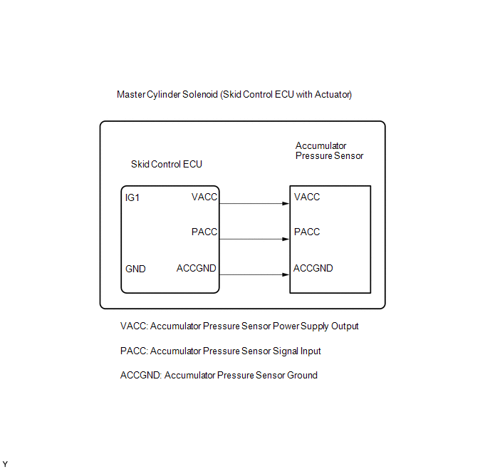
The accumulator pressure sensor is connected to the skid control ECU in the master cylinder solenoid.
|
DTC No. |
DTC Detecting Condition |
Trouble Areas |
|---|---|---|
|
C1254 |
Accumulator pressure sensor fault (Fluid pressure does not change when it should e.g. pump operates, brake pedal depressed/released). |
|
PROCEDURE
|
1. |
READ VALUE USING DATA LIST (ACCUMULATOR SENSOR) |
(a) Connect Techstream to the DLC3.
(b) Turn the ignition switch to OFF.
(c) Depress the brake pedal more than 20 times.
(d) Turn the ignition switch to the ON position.
(e) Select the Data List mode on the Techstream.
ABS/VSC/TRAC|
Tester Display |
Measurement Item / Range |
Normal Condition |
Diagnostic Note |
|---|---|---|---|
|
Accumulator Sensor |
Accumulator pressure sensor reading / min.: 0 V, max.: 5 V |
3.58 to 5 V |
- |
(f) Confirm whether the accumulator output voltage is normal.
|
Result |
Proceed to |
|---|---|
|
Output value normal |
A |
|
Output value not normal |
B |
| B | .gif) |
REPLACE MASTER CYLINDER SOLENOID |
|
.gif)
|
2. |
READ VALUE USING DATA LIST (MASTER CYLINDER PRESSURE SENSOR) |
(a) Turn the ignition switch to OFF.
(b) Depress the brake pedal more than 20 times.
(c) Install a brake pedal effort gauge (SST), and bleed air.
(d) Connect Techstream to the DLC3.
(e) Turn the ignition switch to the ON position.
(f) Select the Data List mode on the Techstream.
ABS/VSC/TRAC|
Tester Display |
Measurement Item / Range |
Normal Condition |
Diagnostic Note |
|---|---|---|---|
|
Master Cylinder Sensor |
Master cylinder pressure sensor reading / min.: 0 V, max.: 5 V |
0.3 to 1.9 V With pedal pressure of 49 N (5 kgf, 11 lbf) |
Front brake pressure: 770 to 1280 kPa (7.9 to 13.1 kgf/cm2, 112 to 186 psi) |
(g) Check that the master cylinder output value is in the Normal Condition range.
OK:
Master cylinder pressure sensor value is in the Normal Condition.
| NG | |
REPLACE MASTER CYLINDER SOLENOID |
|
|
3. |
RECONFIRM DTC |
(a) Clear the DTCs (See page .gif) ).
).
(b) Turn the ignition switch to OFF.
(c) Depress the brake pedal more than 20 times.
(d) Turn the ignition switch to the ON position.
(e) Wait until the pump motor stops.
(f) Depress the brake pedal and release it.
(g) Wait for 25 minutes.
(h) Check if the same DTCs are recorded.
|
Result |
Proceed to |
|---|---|
|
DTC output |
A |
|
DTC not output |
B |
| A | |
REPLACE MASTER CYLINDER SOLENOID |
| B | |
END |
 Pump Motor Relay (C1253)
DESCRIPTION
The motor relay (semiconductor relay) is built into the master cylinder solenoid
and drives the pump motor based on a signal from the skid control ECU (master cylinder
solenoid).
...
 Accumulator Low Pressure (C1256)
DESCRIPTION
The accumulator pressure sensor is connected to the skid control ECU in the master
cylinder solenoid.
DTC No.
DTC Detecting Condition
Trouble Areas
...
Other materials:
Dtc Check / Clear
DTC CHECK / CLEAR
1. START DIAGNOSTIC MODE
HINT:
Illustrations may differ from the actual vehicle screen depending on
the device settings and options. Therefore, some detailed areas may not
be shown exactly the same as on the actual vehicle screen.
If the system cannot enter d ...
Reassembly
REASSEMBLY
CAUTION / NOTICE / HINT
HINT:
Use the same procedure for the RH side and LH side.
The following procedure is for the LH side.
When installing a new front wheel opening extension pad or No. 1 front
wheel opening extension pad or No. 2 front wheel opening extension pa ...
Problem Symptoms Table
PROBLEM SYMPTOMS TABLE
NOTICE:
After replacing the stereo component tuner assembly of vehicles subscribed to
pay-type satellite radio broadcasts, XM radio ID registration is necessary (w/ SDARS
System).
HINT:
Use the table below to help determine the cause of problem symptoms.
If ...
