Toyota Tacoma (2015-2018) Service Manual: Blind Spot Monitor Sensor Communication Stop Mode
DESCRIPTION
|
Detection Item |
Symptom |
Trouble Area |
|---|---|---|
|
Blind Spot Monitor Sensor Communication Stop Mode |
Either Condition is met:
|
|
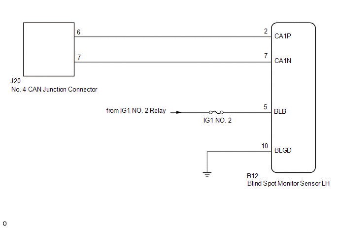
WIRING DIAGRAM
CAUTION / NOTICE / HINT
CAUTION:
When performing the confirmation driving pattern, obey all speed limits and traffic laws.
NOTICE:
- Because the order of diagnosis is important to allow correct diagnosis,
make sure to begin troubleshooting using How to Proceed with Troubleshooting
when CAN communication system related DTCs are output.
Click here
.gif)
- Before measuring the resistance of the CAN bus, turn the ignition switch off and leave the vehicle for 1 minute or more without operating the key or any switches, or opening or closing the doors. After that, disconnect the cable from the negative (-) battery terminal and leave the vehicle for 1 minute or more before measuring the resistance.
- After turning the ignition switch off, waiting time may be required
before disconnecting the cable from the negative (-) battery terminal. Therefore,
make sure to read the disconnecting the cable from the negative (-) battery
terminal notices before proceeding with work.
Click here
- Some parts must be initialized and set when replacing or removing and
installing parts.
Click here
- After performing repairs, perform the DTC check procedure and confirm
that the DTCs are not output again.
DTC check procedure: Turn the ignition switch to ON and wait for 1 minute or more. Then operate the suspected malfunctioning system and drive the vehicle at 60 km/h (37 mph) or more for 5 minutes or more.
- After the repair, perform the CAN bus check and check that all the ECUs
and sensors connected to the CAN communication system are displayed as normal.
Click here
- Inspect the fuses for circuits related to this system before performing the following procedure.
HINT:
- Before disconnecting related connectors for inspection, push in on each connector body to check that the connector is not loose or disconnected.
- When a connector is disconnected, check that the terminals and connector body are not cracked, deformed or corroded.
PROCEDURE
|
1. |
CHECK FOR OPEN IN CAN BUS LINES (BLIND SPOT MONITOR SENSOR LH CAN BRANCH LINE) |
|
(a) Disconnect the cable from the negative (-) battery terminal. |
|
(b) Disconnect the blind spot monitor sensor LH connector.
(c) Measure the resistance according to the value(s) in the table below.
Standard Resistance:
|
Tester Connection |
Condition |
Specified Condition |
|---|---|---|
|
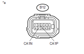
B12-2 (CA1P) - B12-7 (CA1N) |
Cable disconnected from negative (-) battery terminal |
54 to 69 Ω |
|
*a |
Front view of wire harness connector (to Blind Spot Monitor Sensor LH) |
| NG | .gif) |
REPAIR OR REPLACE CAN BRANCH LINE OR CONNECTOR (BLIND SPOT MONITOR SENSOR LH) |
|
.gif)
|
2. |
CHECK HARNESS AND CONNECTOR (POWER SOURCE CIRCUIT) |
|
(a) Measure the resistance according to the value(s) in the table below. Standard Resistance:
|
|
(b) Connect the cable to the negative (-) battery terminal.
(c) Measure the voltage according to the value(s) in the table below.
Standard Voltage:
|
Tester Connection |
Switch Condition |
Specified Condition |
|---|---|---|
|
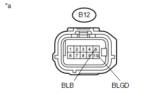
B12-5 (BLB) - Body ground |
Ignition switch ON |
11 to 14 V |
|
*a |
Front view of wire harness connector (to Blind Spot Monitor Sensor LH) |
| OK | |
REPLACE BLIND SPOT MONITOR SENSOR LH |
| NG | |
REPAIR OR REPLACE HARNESS OR CONNECTOR |
 4WD Control ECU Communication Stop Mode
DESCRIPTION
Detection Item
Symptom
Trouble Area
4WD Control ECU Communication Stop Mode
Either condition is met:
Communicati ...
 Radio Receiver Assembly Communication Stop Mode
DESCRIPTION
Detection Item
Symptom
Trouble Area
Radio Receiver Assembly Communication Stop Mode
Either condition is met:
Com ...
Other materials:
Tire Pressure Monitor ECU Communication Stop Mode
DESCRIPTION
Detection Item
Symptom
Trouble Area
Tire Pressure Monitor ECU Communication Stop Mode
Either condition is met:
Communication stop for "Tire Pressure2" is indicated on the
"Communication Bus C ...
Installation
INSTALLATION
PROCEDURE
1. INSTALL ENGINE WATER PUMP ASSEMBLY
(a) Install the engine water pump assembly and a new gasket to the timing
chain cover assembly with the 15 bolts.
Torque:
for Bolt A and B :
11 N·m {112 kgf·cm, 8 ft·lbf}
for Bolt C :
21 N·m {214 kgf ...
Problem Symptoms Table
PROBLEM SYMPTOMS TABLE
HINT:
Use the table below to help determine the cause of the problem symptom.
The potential causes of the symptoms are listed in order of probability
in the "Suspected Area" column of the table. Check each symptom by checking
the suspected areas ...
