Toyota Tacoma (2015-2018) Service Manual: Pressure Control Solenoid "G" Electrical (Shift Solenoid Valve SL4) (P2810)
DESCRIPTION
Changing from 1st to 6th is performed by the ECM turning shift solenoid valves
SL1, SL2, SL3 and SL4 on and off. If an open or short circuit occurs in any of the
shift solenoid valves, the ECM controls the remaining normal shift solenoid valves
to allow the vehicle to be operated (See page .gif) )
)
|
DTC No. |
DTC Detection Condition |
Trouble Area |
|---|---|---|
|
P2810 |
An open or short circuit (output signal duty is 0% or 100%) is detected by the ECM in the shift solenoid valve SL4 circuit while driving and shifting gears (SL4 output signal duty is more than 3% and less than 100% under normal conditions) (1 trip detection logic). |
|
MONITOR DESCRIPTION
This DTC indicates an open or short in the shift solenoid valve SL4 circuit. The ECM commands gear shifts by turning the shift solenoid valves on or off. When there is an open or short circuit in any of the shift solenoid valve circuits, the ECM detects the problem and illuminates the MIL and stores the DTC. The ECM also performs the fail-safe function and turns the other normal shift solenoid valves on or off. (In case of an open or short circuit, the ECM stops sending current to the circuit.)
While driving and shifting gears, if the ECM detects an open or short in the
shift solenoid valve SL4 circuit, the ECM determines there is a malfunction (See
page ).
MONITOR STRATEGY
|
Related DTCs |
P2810: Shift solenoid valve SL4/Range check |
|
Required sensors/Components |
Shift solenoid valve SL4 |
|
Frequency of operation |
Continuous |
|
Duration |
1 sec. |
|
MIL operation |
Immediately |
|
Sequence of operation |
None |
TYPICAL ENABLING CONDITIONS
All:|
The monitor will run whenever the following DTCs are not stored |
None |
|
Ignition switch |
ON |
|
Starter |
OFF |
|
Battery voltage |
12 V or higher |
|
Battery voltage |
10 V or higher, and below 12 V |
|
Target current |
Below 0.75 A |
|
Battery voltage |
8 V or higher |
|
Target current |
0.25 A or higher |
TYPICAL MALFUNCTION THRESHOLDS
One of the following conditions is met: Condition (A), (B) or (C)
Condition (A) and (B):|
Output duty cycle |
100% or more |
|
Output duty cycle |
0% or less |
COMPONENT OPERATING RANGE
|
Output duty cycle |
More than 3%, and less than 100% |
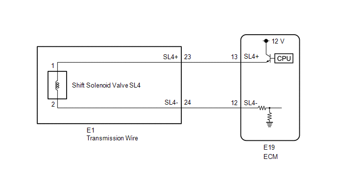
WIRING DIAGRAM
CAUTION / NOTICE / HINT
NOTICE:
- Perform the universal trip to clear permanent DTCs (See page
).
- Perform registration and/or initialization when parts related to the
automatic transmission are replaced (See page
).
HINT:
- The following table shows normal operation of the shift solenoid valve
SL4 when the shift lever is in D:
ECM commanded gear
1st
2nd
3rd
4th
5th
6th
Shift solenoid valve SL4
OFF
OFF
ON
OFF
ON
OFF
- After the repair, clear the DTCs and perform the following procedure
to check that DTCs are not output.
- Perform the D Position Shift Test in Road Test (See page
).
- Check for DTCs again (See page
).
- Perform the D Position Shift Test in Road Test (See page
PROCEDURE
|
1. |
INSPECT TRANSMISSION WIRE (SHIFT SOLENOID VALVE SL4) |
|
(a) Disconnect the E1 transmission wire connector. |
|
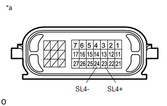
(b) Measure the resistance according to the value(s) in the table below.
Standard Resistance:
|
Tester Connection |
Condition |
Specified Condition |
|---|---|---|
|
23 (SL4+) - 24 (SL4-) |
20°C (68°F) |
5.0 to 5.6 Ω |
|
23 (SL4+) - Body ground |
Always |
10 kΩ or higher |
|
24 (SL4-) - Body ground |
Always |
10 kΩ or higher |
|
*a |
Component without harness connected (Transmission Wire) |
| NG | .gif) |
GO TO STEP 3 |
|
.gif)
|
2. |
CHECK HARNESS AND CONNECTOR (TRANSMISSION WIRE - ECM) |
|
(a) Disconnect the ECM connector. |
|
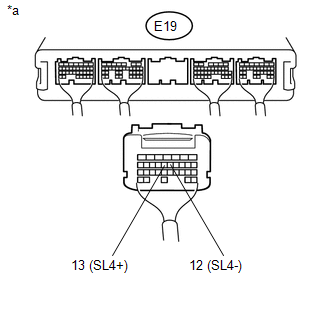
(b) Measure the resistance according to the value(s) in the table below.
Standard Resistance:
|
Tester Connection |
Condition |
Specified Condition |
|---|---|---|
|
E19-13 (SL4+) - E19-12 (SL4-) |
20°C (68°F) |
5.0 to 5.6 Ω |
|
E19-13 (SL4+) - Body ground |
Always |
10 kΩ or higher |
|
E19-12 (SL4-) - Body ground |
Always |
10 kΩ or higher |
|
*a |
Rear view of wire harness connector (to ECM) |
| OK | |
REPLACE ECM |
| NG | |
REPAIR OR REPLACE HARNESS OR CONNECTOR |
|
3. |
INSPECT SHIFT SOLENOID VALVE SL4 |
|
(a) Remove shift solenoid valve SL4 (See page
|
|
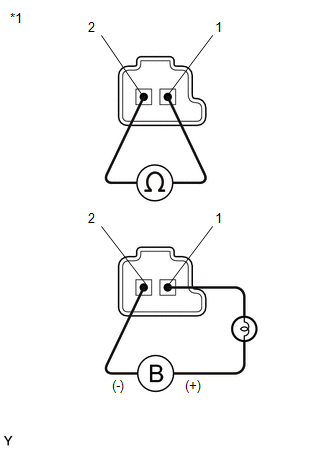
(b) Measure the resistance according to the value(s) in the table below.
Standard Resistance:
|
Tester Connection |
Condition |
Specified Condition |
|---|---|---|
|
1 - 2 |
20°C (68°F) |
5.0 to 5.6 Ω |
(c) Apply 12 V battery voltage to the shift solenoid valve and check that the valve moves and makes an operating noise.
OK:
|
Measurement Condition |
Specified Condition |
|---|---|
|
Valve moves and makes an operating noise |
|
*1 |
Shift Solenoid Valve SL4 |
| OK | |
REPLACE TRANSMISSION WIRE |
| NG | |
REPLACE SHIFT SOLENOID VALVE SL4 |
 Pressure Control Solenoid "G" Performance (Shift Solenoid Valve SL4) (P2808)
SYSTEM DESCRIPTION
The ECM uses the vehicle speed signal and signals from the transmission revolution
sensors (NT, SP2) to detect the actual gear (1st, 2nd, 3rd, 4th, 5th or 6th gear).
The ECM com ...
 Pressure Control Solenoid "C" Electrical (Shift Solenoid Valve SL3) (P0798)
DESCRIPTION
Changing from 1st to 6th is performed by the ECM turning shift solenoid valves
SL1, SL2, SL3 and SL4 on and off. If an open or short circuit occurs in any of the
shift solenoid valves ...
Other materials:
Skid Control Buzzer Circuit (C1A4A)
DESCRIPTION
The millimeter wave radar sensor assembly is connected to the forward recognition
camera via CAN communication.
The millimeter wave radar sensor assembly operates the pre-collision alarm by
sending a buzzer request signal to the skid control buzzer.
If the millimeter wave radar se ...
Reassembly
REASSEMBLY
CAUTION / NOTICE / HINT
CAUTION:
Wear protective gloves. Sharp areas on the parts may injure your hands.
PROCEDURE
1. INSTALL SEPARATE TYPE REAR SEATBACK COVER
(a) Using hog ring pliers, install the separate type rear seatback cover
with 2 new hog rings.
Text in Il ...
Precaution
PRECAUTION
1. PRECAUTIONS FOR REFRIGERANT HFO-1234yf (R1234yf)
(a) Compatibility
(1) The parts used in the refrigerant cycle, the compressor oil, etc. of the
HFO-1234yf (R1234yf) system are not compatible with the conventional HFC-134a (R134a)
system.
(b) HFO-1234yf (R1234yf) Refrigerant
(1 ...
