Toyota Tacoma (2015-2018) Service Manual: Parking Brake System
Adjustment
ADJUSTMENT
PROCEDURE
1. INSPECT PARKING BRAKE LEVER TRAVEL
(a) Fully pull the parking brake lever to engage the parking brake.
(b) Release the lever to disengage the parking brake.
(c) Slowly pull the parking brake lever all the way and count the number of clicks.
Standard parking brake lever travel when pulled with a force of 200 N (20 kgf, 45 lbf):
5 to 7 clicks
If the parking brake lever travel is not as specified, adjust the parking brake shoe clearance and parking brake lever travel.
2. REMOVE REAR WHEEL
3. ADJUST PARKING BRAKE LEVER TRAVEL
(a) Remove the rear console box assembly (See page
.gif) ).
).
(b) Completely release the parking brake lever.
|
(c) Loosen the adjusting nut to completely release the parking brake cable. |
|
(d) Temporarily install the hub nuts.
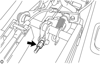
(e) Remove the hole plug.
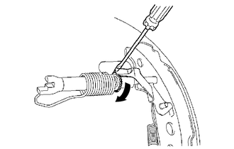
(f) Using a screwdriver, turn the shoe adjuster to expand the shoe until the brake drum locks.
.png) |
Shoe Adjuster Expands |
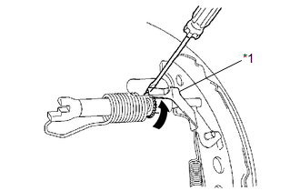
(g) Using another screwdriver, push up the automatic adjust lever and turn the shoe adjuster to contract the shoes so that the shoe does not touch the brake drum. Then turn the shoe adjuster another 180 degrees to further contract the shoes.
|
*1 |
Automatic Adjust Lever |
|
|
Shoe Adjuster Contracts |
(h) Check that there is no brake drag against the shoe.
(i) Install the hole plug.
(j) Remove the hub nuts.
|
(k) Turn the adjusting nut until the parking brake lever travel becomes correct. Standard parking brake lever travel when pulled with a force of 200 N (20 kgf, 45 lbf): 5 to 7 clicks |
|
(l) Operate the parking brake lever 3 to 4 times and check the parking brake lever travel.
Standard parking brake lever travel when pulled with a force of 200 N (20 kgf, 45 lbf):
5 to 7 clicks
(m) Check whether the parking brake drags or not.
(n) When operating the parking brake lever, check that the parking brake warning light comes on.
Standard:
The parking brake warning light always illuminates at the first click.
(o) Install the rear console box assembly (See page
).
4. INSTALL REAR WHEEL
Torque:
113 N·m {1152 kgf·cm, 83 ft·lbf}
Problem Symptoms Table
PROBLEM SYMPTOMS TABLE
HINT:
Use the table below to help determine the cause of problem symptoms. If multiple suspected areas are listed, the potential causes of the symptoms are listed in order of probability in the "Suspected Area" column of the table. Check each symptom by checking the suspected areas in the order they are listed. Replace parts as necessary.
Parking Brake System|
Symptom |
Suspected Area |
See page |
|---|---|---|
|
Brake drag |
Parking brake lever travel (Out of adjustment) |
|
|
Parking brake cable (Sticking) |
|
|
|
Parking brake shoe clearance (Out of adjustment) |
|
|
|
Parking brake shoe lining (Cracked or distorted) |
|
|
|
Tension or return spring (Damaged) |
|
.gif)
 Parking Brake Switch
Components
COMPONENTS
ILLUSTRATION
Inspection
INSPECTION
PROCEDURE
1. INSPECT PARKING BRAKE SWITCH ASSEMBLY
(a) Check the resistance.
(1) Measure the resistance according to the value(s) ...
 2gr-fks Charging
...
Other materials:
Diagnostic Trouble Code Chart
DIAGNOSTIC TROUBLE CODE CHART
Manual Transmission System
DTC Code
Detection Item
MIL
Memory
See page
P03352A
Crankshaft Position Sensor "A" Signal Stuck in Range
Does not come on
DTC ...
Transmitter ID1 Operation Stop (C2111/11-C2114/14)
DESCRIPTION
The tire pressure warning valve and transmitters that are installed in the tire
and wheel assemblies measure the tire pressure of each wheel. The measured values
are transmitted to the tire pressure warning ECU and receiver in the vehicle as
radio waves. The ECU compares the measu ...
Installation
INSTALLATION
PROCEDURE
1. INSTALL AUTO HIGH BEAM SWITCH
(a) Attach the 2 claws to install the auto high beam switch to the instrument
panel lower finish panel sub-assembly.
2. INSTALL INSTRUMENT PANEL LOWER FINISH PANEL SUB-ASSEMBLY
Click here
3. CONNECT HOOD LOCK CONTROL LEVER SUB-ASSEMBL ...
