Toyota Tacoma (2015-2018) Service Manual: P/W Master Switch Communication Stop (B1206)
DESCRIPTION
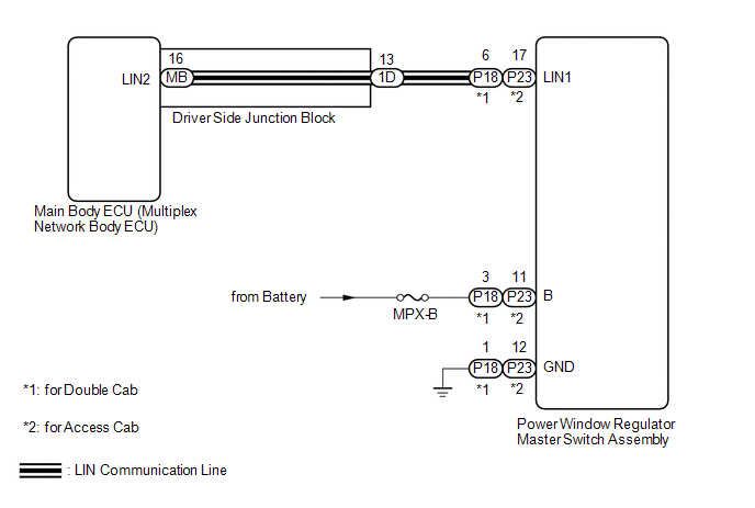
This DTC is stored when LIN communication between the power window regulator master switch assembly and main body ECU (multiplex network body ECU) stops for 10 seconds or more.
|
DTC No. |
DTC Detection Condition |
Trouble Area |
|---|---|---|
|
B1206 |
No communication between power window regulator master switch assembly and main body ECU (multiplex network body ECU) for 10 seconds or more. |
|
WIRING DIAGRAM
CAUTION / NOTICE / HINT
NOTICE:
- Inspect the fuses for circuits related to this system before performing the following inspection procedure.
- If the main body ECU (multiplex network body ECU) is replaced, refer
to Registration (See page
.gif) )
)
PROCEDURE
|
1. |
INSPECT DRIVER SIDE JUNCTION BLOCK |
(a) Remove the driver side junction block (See page
).
(b) Remove the main body ECU (multiplex network body ECU) from the driver side junction block.
(c) Measure the resistance according to the value(s) in the table below.
.png)
Standard Resistance:
|
Tester Connection |
Condition |
Specified Condition |
|---|---|---|
|
1D-13 - MB-16 (LIN2) |
Always |
Below 1 Ω |
|
*a |
Component without harness connected (Driver Side Junction Block) |
- |
- |
HINT:
This inspection is to check the LIN line in the driver side junction block that connects the wire harness to the built-in main body ECU (multiplex network body ECU).
| NG | .gif) |
REPLACE DRIVER SIDE JUNCTION BLOCK |
|
.gif)
|
2. |
CHECK HARNESS AND CONNECTOR (DRIVER SIDE JUNCTION BLOCK - POWER WINDOW REGULATOR MASTER SWITCH ASSEMBLY) |
(a) for Double Cab
(1) Disconnect the 1D driver side junction block connector.
(2) Disconnect the P18 power window regulator master switch assembly connector.
(3) Measure the resistance according to the value(s) in the table below.
Standard Resistance:
|
Tester Connection |
Condition |
Specified Condition |
|---|---|---|
|
1D-13 - P18-6 (LIN1) |
Always |
Below 1 Ω |
|
1D-13 or P18-6 (LIN1) - Body ground |
Always |
10 kΩ or higher |
(b) for Access Cab
(1) Disconnect the 1D driver side junction block connector.
(2) Disconnect the P23 power window regulator master switch assembly connector.
(3) Measure the resistance according to the value(s) in the table below.
Standard Resistance:
|
Tester Connection |
Condition |
Specified Condition |
|---|---|---|
|
1D-13 - P23-17 (LIN1) |
Always |
Below 1 Ω |
|
1D-13 or P23-17 (LIN1) - Body ground |
Always |
10 kΩ or higher |
| NG | |
REPAIR OR REPLACE HARNESS OR CONNECTOR |
|
|
3. |
CHECK HARNESS AND CONNECTOR (POWER WINDOW REGULATOR MASTER SWITCH - POWER SOURCE CIRCUIT) |
(a) for Double Cab
(1) Disconnect the P18 power window regulator master switch assembly connector.
(2) Measure the voltage according to the value(s) in the table below.
Standard Voltage:
|
Tester Connection |
Condition |
Specified Condition |
|---|---|---|
|
P18-3 (B) - P18-1 (GND) |
Always |
11 to 14 V |
(3) Measure the resistance according to the value(s) in the table below.
Standard Resistance:
|
Tester Connection |
Condition |
Specified Condition |
|---|---|---|
|
P18-1 (GND) - Body ground |
Always |
Below 1 Ω |
(b) for Access Cab
(1) Disconnect the P23 power window regulator master switch assembly connector.
(2) Measure the voltage according to the value(s) in the table below.
Standard Voltage:
|
Tester Connection |
Condition |
Specified Condition |
|---|---|---|
|
P23-11 (B) - P23-12 (GND) |
Always |
11 to 14 V |
(3) Measure the resistance according to the value(s) in the table below.
Standard Resistance:
|
Tester Connection |
Condition |
Specified Condition |
|---|---|---|
|
P23-12 (GND) - Body ground |
Always |
Below 1 Ω |
| NG | |
REPAIR OR REPLACE HARNESS OR CONNECTOR |
|
|
4. |
REPLACE POWER WINDOW REGULATOR MASTER SWITCH ASSEMBLY |
(a) Replace the power window regulator master switch assembly.
|
|
5. |
CHECK DTC OUTPUT |
(a) Clear the DTCs (See page ).
(b) Recheck for DTCs.
OK:
DTC B1206 is not output.
| OK | |
END (POWER WINDOW REGULATOR MASTER SWITCH ASSEMBLY WAS DEFECTIVE) |
| NG | |
REPLACE MAIN BODY ECU (MULTIPLEX BODY ECU) |
 LIN Communication Bus Malfunction (B2325)
DESCRIPTION
The main body ECU (multiplex network body ECU) monitors communication between
all the ECUs connected to the door bus lines. When the main body ECU (multiplex
network body ECU) detects ...
 Lost Communication with Power Source Control (B278C)
DESCRIPTION
DTC No.
DTC Detection Condition
Trouble Area
B278C
An internal malfunction occurs in the certification ECU (smart key ECU
...
Other materials:
Diagnostic Trouble Code Chart
DIAGNOSTIC TROUBLE CODE CHART
Central Gateway ECU (Network Gateway ECU)
DTC Code
Detection Item
See page
B1003
ECU Malfunction
...
Installation
INSTALLATION
PROCEDURE
1. INSTALL REAR DIFFERENTIAL DRIVE PINION BEARING SPACER
(a) Install a new front differential drive pinion bearing spacer.
HINT:
Make sure the front differential drive pinion bearing spacer is installed correctly.
2. INSTALL DIFFERENTIAL OIL STORAGE RING
(a) Using a bra ...
System Description
SYSTEM DESCRIPTION
1. GENERAL
(a) The blind spot monitor system has the blind spot monitor function and rear
cross traffic alert function.
(1) Blind spot monitor function
The blind spot monitor function is a function that assists the driver
in making the decision to change lanes. Th ...
