Toyota Tacoma (2015-2018) Service Manual: Parts Location
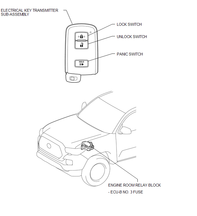
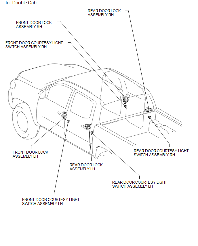
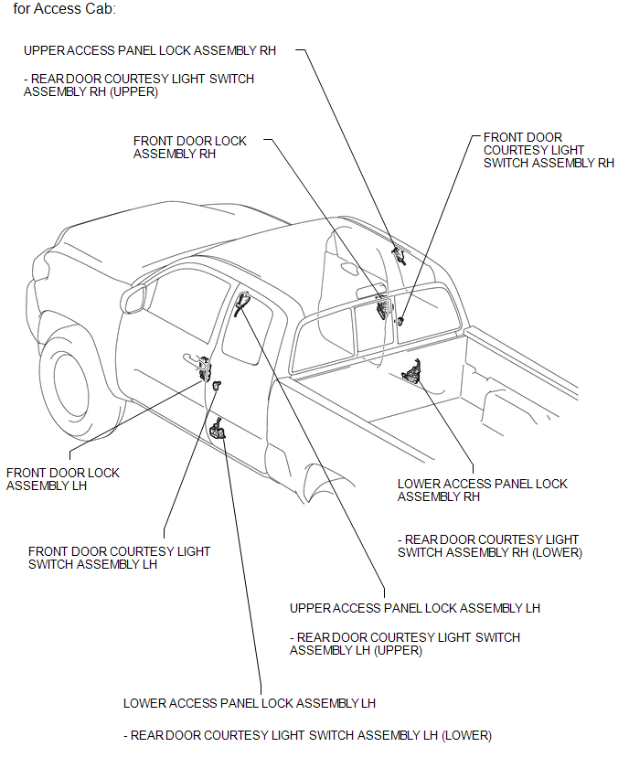
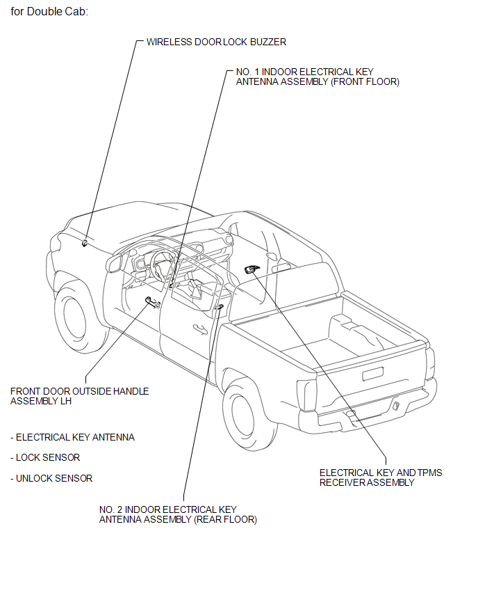
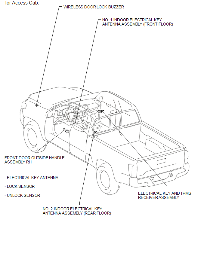
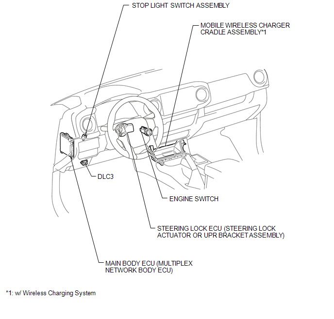
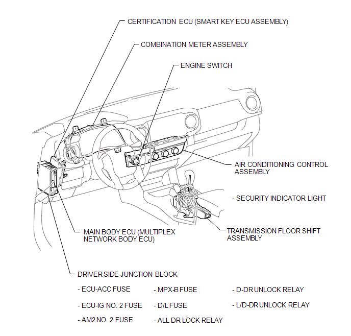
PARTS LOCATION
ILLUSTRATION
ILLUSTRATION
ILLUSTRATION
ILLUSTRATION
ILLUSTRATION
ILLUSTRATION
ILLUSTRATION

 Precaution
PRECAUTION
1. CAUTION REGARDING INTERFERENCE WITH ELECTRONIC DEVICES
CAUTION:
People with implantable cardiac pacemakers, cardiac resynchronization
therapy-pacemakers or implantable car ...
Other materials:
AUTO LSD Indicator Light Remains ON
DESCRIPTION
During normal mode, pressing the VSC OFF switch for a short amount of time changes
vehicle to AUTO LSD mode.
WIRING DIAGRAM
CAUTION / NOTICE / HINT
NOTICE:
When replacing the brake actuator assembly, perform calibration (See page
).
PROCEDURE
1.
CHECK ...
Lost Communication with Brake System Control Module (U0129/29)
DESCRIPTION
The tire pressure warning ECU and receiver receives signals from the skid control
ECU (brake actuator assembly) via the CAN communication system.
DTC No.
DTC Detection Condition
Trouble Area
U0129/29
Lost communication with ...
Seat Position Sensor
Components
COMPONENTS
ILLUSTRATION
On-vehicle Inspection
ON-VEHICLE INSPECTION
PROCEDURE
1. INSPECT SEAT POSITION AIRBAG SENSOR (for Vehicle not Involved in Collision)
(a) Perform a diagnostic system check (See page
).
2. INSPECT SEAT POSITION AIRBAG SENSOR (for Vehicle Involved in C ...
