Toyota Tacoma (2015-2018) Service Manual: On-vehicle Inspection
ON-VEHICLE INSPECTION
PROCEDURE
1. INSPECT AIR CONDITIONER PRESSURE SENSOR (for Automatic Air Conditioning System)
(a) Check the wire harness.
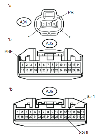
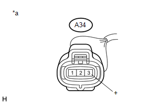
(1) Disconnect the A34 air conditioner pressure sensor connector.
(2) Disconnect the A35 and A36 air conditioning amplifier assembly connector.
|
(3) Measure the resistance according to the value(s) in the table below. Text in Illustration
Standard Resistance:
If the resistance is not as specified, repair the wire harness. |
|
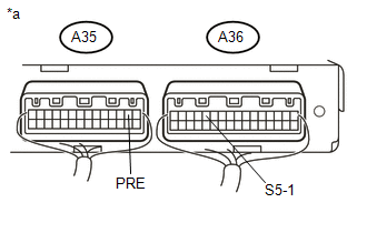
(4) Connect the A35 and A36 air conditioning amplifier assembly connector.
|
(5) Measure the voltage according to the value(s) in the table below. Text in Illustration
Standard Voltage:
If the voltage is not as specified, repair the wire harness or replace the air conditioning amplifier assembly. |
|
(b) Check the air conditioner pressure sensor.
(1) Install a manifold gauge set.
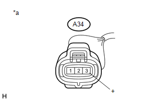
(2) Connect the A34 air conditioner pressure sensor connector.
(3) Warm up the engine.
(4) A/C switch on.
|
(5) Measure the voltage according to the value(s) in the table below. Text in Illustration
Standard Voltage:
If the voltage is not as specified, replace the air conditioner pressure sensor. |
|
2. INSPECT AIR CONDITIONER PRESSURE SENSOR (for Manual Air Conditioning System)
(a) Check the wire harness.
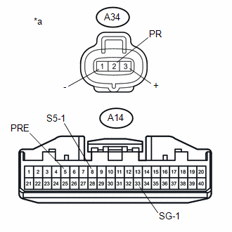
(1) Disconnect the A34 air conditioner pressure sensor connector.
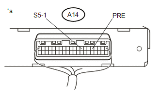
(2) Disconnect the A14 air conditioning amplifier assembly connector.
|
(3) Measure the resistance according to the value(s) in the table below. Text in Illustration
Standard Resistance:
If the resistance is not as specified, repair the wire harness. |
|
(4) Connect the A14 air conditioning amplifier assembly connector.
|
(5) Measure the voltage according to the value(s) in the table below. Text in Illustration
Standard Voltage:
If the voltage is not as specified, repair the wire harness or replace the air conditioning amplifier assembly. |
|
(b) Check the air conditioner pressure sensor.
(1) Install a manifold gauge set.
(2) Connect the A34 air conditioner pressure sensor connector.
(3) Warm up the engine.
(4) A/C switch on.
|
(5) Measure the voltage according to the value(s) in the table below. Text in Illustration
Standard Voltage:
If the voltage is not as specified, replace the air conditioner pressure sensor. |
|
 Installation
INSTALLATION
PROCEDURE
1. INSTALL AIR CONDITIONER PRESSURE SENSOR
(a) Remove the vinyl tape from the air conditioner tube and accessory assembly
and connecting part of the air conditioner pressur ...
 Removal
REMOVAL
PROCEDURE
1. REMOVE REFRIGERANT FROM REFRIGERATION SYSTEM
2. REMOVE AIR CONDITIONER PRESSURE SENSOR
(a) Disconnect the connector.
...
Other materials:
Anti-glare inside rear view mirror
Glare from the headlights of vehicles behind can be reduced by using the following
functions.
Manual anti-glare inside rear view
mirror
Normal position
Anti-glare position
Auto anti-glare inside rear view
mirror (type A)
In automatic mode, sensors are used to detect the headlights of ...
Reporting safety defects for U.S. owners
If you believe that your vehicle has a defect which could cause a crash or could
cause injury or death, you should immediately inform the National Highway Traffic
Safety Administration (NHTSA) in addition to notifying Toyota Motor Sales, U.S.A.,
Inc. (Toll-free: 1-800-331-4331).
If NHTSA rece ...
Transfer Shift Motor Limit Switch Circuit (P17AC)
DESCRIPTION
When the transfer switches modes, the TL1, TL2 and TL3 terminals of the limit
switch are in one of the ON/OFF combinations listed in the table below.
Terminal
When 2WD
Switching between 2WD and H4
When H4
Switching between H4 and ...
