Toyota Tacoma (2005–2015) Owners Manual: Anti-glare inside rear view mirror
Glare from the headlights of vehicles behind can be reduced by using the following functions.
 Manual anti-glare inside rear view
mirror
Manual anti-glare inside rear view
mirror
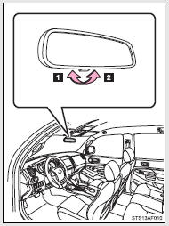
 Normal position
 Anti-glare position
 Auto anti-glare inside rear view
mirror (type A)
Auto anti-glare inside rear view
mirror (type A)
In automatic mode, sensors are used to detect the headlights of vehicles behind and automatically reduces the reflected light.
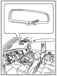
Turns automatic mode on/off
The indicator comes on when automatic mode is turned on.
The mirror will revert to the automatic mode each time the engine switch is turned on.
 Auto anti-glare inside rear view
mirror (type B)
Auto anti-glare inside rear view
mirror (type B)
In automatic mode, sensors are used to detect the headlights of vehicles behind and automatically reduces the reflected light.
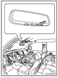
Turns automatic mode on/off
The indicator comes on when automatic mode is turned on.
The mirror will revert to the automatic mode each time the engine switch is turned on.
Adjusting the height of rear view mirror
Adjust the height of the rear view mirror by moving it up and down.
Inside rear view mirror display (vehicles with auto anti-glare inside rear view mirror)
The inside rear view mirror displays the following information.
■ Compass
■ Garage door opener
■To prevent sensor error (vehicles with auto anti-glare inside rear view mirror)
To ensure that the sensors operate properly, do not touch or cover them.
CAUTION
■Caution while driving
Do not adjust the position of the mirror while driving.
Doing so may lead to mishandling of the vehicle and cause an accident, resulting in death or serious injury.
 Steering wheel
The steering wheel can be adjusted to a comfortable position.
Hold the steering wheel and press the lever down.
Adjust to the ideal position by moving the steering wheel horizontally and vertica ...
 Outside rear view mirrors
Mirror angle can be adjusted.
Power-adjustable type
Select a mirror to adjust.
(L: left or R: right)
Adjust the mirror up, down, in or
out using the switch.
Manually adjustable type ...
Other materials:
Precaution
PRECAUTION
PRECAUTION FOR DISCONNECTING CABLE FROM NEGATIVE BATTERY TERMINAL
NOTICE:
When disconnecting the cable from the negative (-) battery terminal,
initialize the following systems after the cable is reconnected.
Click here
If the battery has been discharged and char ...
Dtc Check / Clear
DTC CHECK / CLEAR
1. DTC CHECK / CLEAR (when Using Techstream)
(a) Check for DTCs.
(1) Connect the Techstream to the DLC3.
(2) Turn the ignition switch to ON.
(3) Turn the Techstream on.
(4) Enter the following menus: Chassis / ABS/VSC/ TRAC / Trouble Codes.
(5) Read the DTCs by following the ...
Air Conditioning Amplifier
Components
COMPONENTS
ILLUSTRATION
Installation
INSTALLATION
PROCEDURE
1. INSTALL AIR CONDITIONING AMPLIFIER ASSEMBLY
(a) Install the air conditioner amplifier assembly with the 2 bolts.
Torque:
7.0 N·m {71 kgf·cm, 62 in·lbf}
(b) Connect the 2 connectors.
2. INSTALL INSTRUMENT L ...
