Toyota Tacoma (2015-2018) Service Manual: Rear Power Outlet Socket
Components
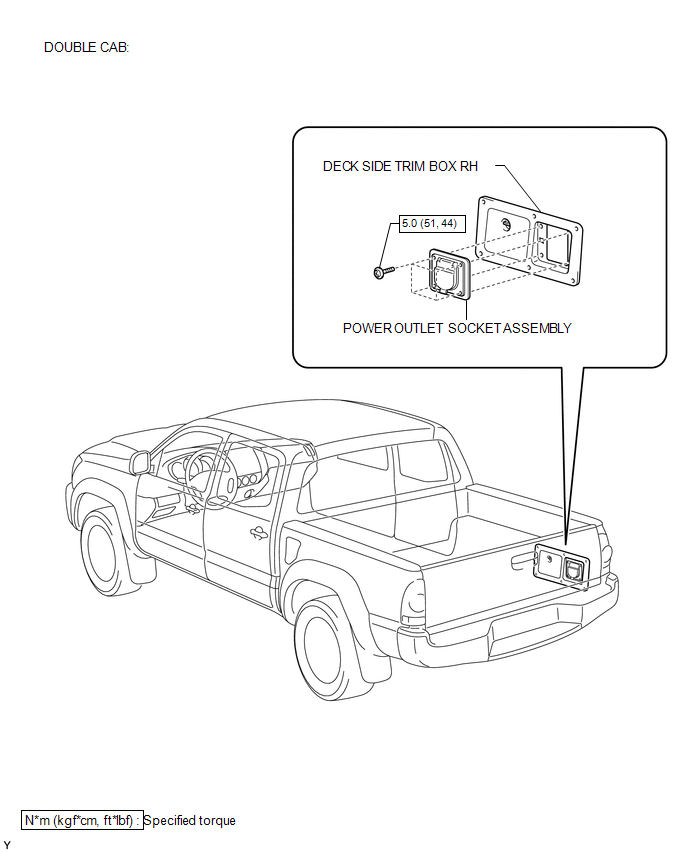
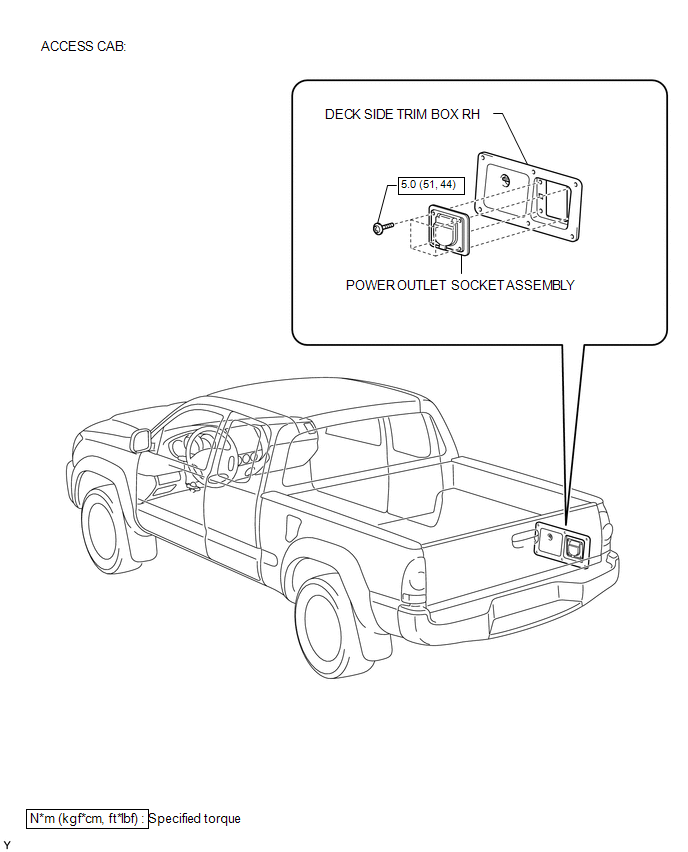
COMPONENTS
ILLUSTRATION
ILLUSTRATION
Installation
INSTALLATION
PROCEDURE
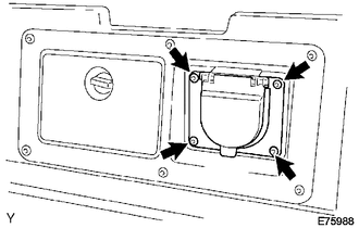
1. INSTALL POWER OUTLET SOCKET ASSEMBLY
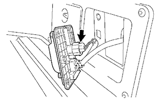
(a) Install the clamp.
(b) Connect the connector.
|
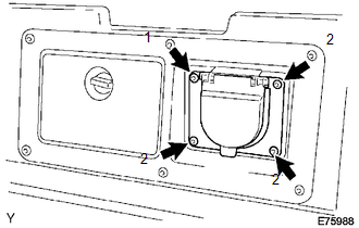
(c) Using a torx socket wrench T30, install the 4 screws and the power outlet socket assembly. Torque: 5.0 N·m {51 kgf·cm, 44 in·lbf} NOTICE: Install the screws in the order shown the illustration. |
|
2. CONNECT CABLE TO NEGATIVE BATTERY TERMINAL
Torque:
5.4 N·m {55 kgf·cm, 48 in·lbf}
Removal
REMOVAL
PROCEDURE
1. DISCONNECT CABLE FROM NEGATIVE BATTERY TERMINAL
2. REMOVE POWER OUTLET SOCKET ASSEMBLY
(a) Using a torx socket wrench T30, remove the 4 screws.
|
(b) Disconnect the connector. |
|
.png)
(c) Remove the clamp and the power outlet socket assembly.
 Power Outlet Socket(for Rear Side)
Components
COMPONENTS
ILLUSTRATION
*1
USB CHARGER SOCKET
-
-
Removal
REMOVAL
PROCEDURE
1. REMOVE REAR CONSOLE BOX ASSEMBLY
Click here ...
 Rear Power Outlet Switch
Components
COMPONENTS
ILLUSTRATION
Inspection
INSPECTION
PROCEDURE
1. INSPECT MAIN SWITCH ASSEMBLY
(a) Check the main switch assembly.
(1) Measure the resistance according to ...
Other materials:
Dtc Check / Clear
DTC CHECK / CLEAR
1. CHECK FOR DTC
HINT:
When using the Techstream with the engine switch off, connect the Techstream
to the DLC3 and turn a courtesy light switch on and off at intervals of 1.5 seconds
or less until communication between the Techstream and the vehicle begins. Then
select th ...
How To Proceed With Troubleshooting
CAUTION / NOTICE / HINT
HINT:
Perform the following procedure to troubleshoot the dynamic radar cruise
control system.
*: Use the Techstream.
PROCEDURE
1.
VEHICLE BROUGHT TO WORKSHOP
NEXT
...
Inspection
INSPECTION
PROCEDURE
1. INSPECT PROPELLER SHAFT WITH CENTER BEARING ASSEMBLY
(a) Using a dial indicator, check the propeller shaft runout.
Maximum runout:
0.6 mm (0.0236 in.)
If the shaft runout is greater than the maximum, replace the shaft.
2. INSPECT PROPELLER SHAFT
(a) Using a dial ...
