Toyota Tacoma (2015-2018) Service Manual: Mute Signal Circuit between Radio Receiver and Stereo Component Amplifier
DESCRIPTION
This circuit sends a signal to the stereo component amplifier assembly to mute noise. Because of that, the noise produced by changing the sound source ceases.
If there is an open in the circuit, noise can be heard from the speakers when changing the sound source.
If there is a short in the circuit, even though the stereo component amplifier assembly is functioning normally, no sound or only an extremely faint sound can be heard.
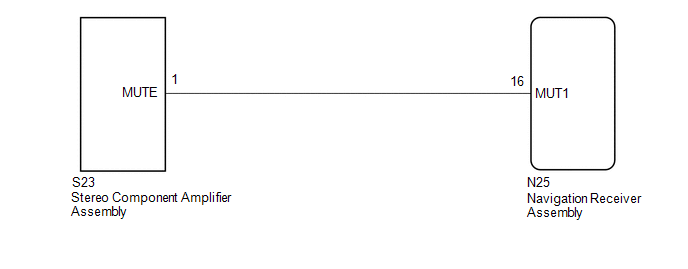
WIRING DIAGRAM
PROCEDURE
|
1. |
INSPECT STEREO COMPONENT AMPLIFIER ASSEMBLY |
(a) Remove the stereo component amplifier assembly with connectors still connected.
|
(b) Measure the voltage according to the value(s) in the table below. Standard Voltage:
|
|
| OK | .gif) |
PROCEED TO NEXT SUSPECTED AREA SHOWN IN PROBLEM SYMPTOMS TABLE |
|
.gif)
|
2. |
CHECK HARNESS AND CONNECTOR (NAVIGATION RECEIVER ASSEMBLY - STEREO COMPONENT AMPLIFIER ASSEMBLY) |
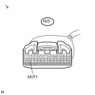
(a) Disconnect the N25 navigation receiver assembly connector.
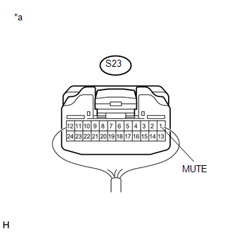
(b) Disconnect the S23 stereo component amplifier assembly connector.
(c) Measure the resistance according to the value(s) in the table below.
Standard Resistance:
|
Tester Connection |
Condition |
Specified Condition |
|---|---|---|
|
N25-16 (MUT1) - S23-1 (MUTE) |
Always |
Below 1 Ω |
|
N25-16 (MUT1) - Body ground |
Always |
10 kΩ or higher |
| NG | |
REPAIR OR REPLACE HARNESS OR CONNECTOR |
|
|
3. |
INSPECT STEREO COMPONENT AMPLIFIER ASSEMBLY (OUTPUT SIGNAL) |
(a) Reconnect the S23 stereo component amplifier assembly connector.
|
(b) Measure the voltage according to the value(s) in the table below. Standard Voltage:
|
|
| OK | |
REPLACE NAVIGATION RECEIVER ASSEMBLY |
| NG | |
REPLACE STEREO COMPONENT AMPLIFIER ASSEMBLY |
 Data Signal Circuit between Navigation Receiver Assembly and Extension Module
DESCRIPTION
The stereo component tuner assembly sends the sound data signal or image data
signal from a device to the navigation receiver assembly via this circuit.
WIRING DIAGRAM
CAUTION / NOT ...
 AVC-LAN Circuit
DESCRIPTION
Each unit of the navigation system connected to the AVC-LAN (communication bus)
transfers the switch signals using the AVC-LAN.
If a short to +B or short to ground occurs in the AVC-LA ...
Other materials:
On-vehicle Inspection
ON-VEHICLE INSPECTION
PROCEDURE
1. INSPECT FRONT AXLE HUB BEARING
(a) Remove the front wheel.
(b) for 4WD:
(1) Remove the front axle hub grease cap (See page
).
(c) Remove the front disc brake caliper (See page
).
(d) Remove the front disc.
(e) Inspect the axle hub backlash.
(1) Usi ...
Diagnostic Trouble Code Chart
DIAGNOSTIC TROUBLE CODE CHART
HINT:
If a trouble code is output during the DTC check, inspect the trouble areas listed
for that code. For details of the code, refer to the "See page".
DTC Code
Detection Item
See page
B1500
F ...
Removal
REMOVAL
PROCEDURE
1. PRECAUTION
NOTICE:
After turning the ignition switch off, waiting time may be required before disconnecting
the cable from the negative (-) battery terminal. Therefore, make sure to read the
disconnecting the cable from the negative (-) battery terminal notices before pr ...
