Toyota Tacoma (2015-2018) Service Manual: On-vehicle Inspection
ON-VEHICLE INSPECTION
PROCEDURE
1. INSPECT FRONT AXLE HUB BEARING
(a) Remove the front wheel.
(b) for 4WD:
(1) Remove the front axle hub grease cap (See page
.gif) ).
).
(c) Remove the front disc brake caliper (See page
).
(d) Remove the front disc.
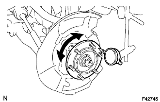
(e) Inspect the axle hub backlash.
(1) Using a dial indicator, check the backlash near the center of the axle hub.
Maximum:
0.05 mm (0.0020 in.)
If the backlash exceeds the maximum, replace the bearing.
|
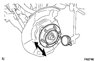
(f) Inspect the axle hub deviation. (1) Using a dial indicator, check the distortion of the surface of the axle hub. Maximum: 0.05 mm (0.0020 in.) If the deviation exceeds the maximum, replace the bearing. |
|
2. INSPECT REAR AXLE HUB BEARING
(a) Remove the rear wheel.
(b) Remove the rear brake drum (See page ).
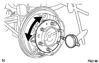
(c) Inspect the axle shaft backlash.
(1) Using a dial indicator, check the backlash near the center of the axle shaft.
Maximum:
0.05 mm (0.0020 in.)
If the backlash exceeds the maximum, replace the bearing.
|
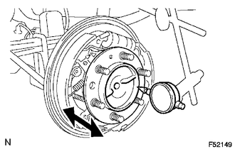
(d) Inspect the axle shaft deviation. (1) Using a dial indicator, check the distortion of the surface of the axle shaft. Maximum: 0.05 mm (0.0020 in.) If the deviation exceeds the maximum, replace the bearing. |
|
 Problem Symptoms Table
PROBLEM SYMPTOMS TABLE
HINT:
Use the table below to help determine the cause of problem symptoms. If multiple
suspected areas are listed, the potential causes of the symptoms are listed in order
...
 Front Axle Hub
...
Other materials:
IG Power Source Circuit
DESCRIPTION
The main power source is supplied to the air conditioning amplifier assembly
when the ignition switch is turned to ON.
The power is used for operating the air conditioning amplifier assembly, servo
motors, etc.
WIRING DIAGRAM
CAUTION / NOTICE / HINT
NOTICE:
Inspect the fuses ...
On-vehicle Inspection
ON-VEHICLE INSPECTION
PROCEDURE
1. INSPECT INDICATOR LIGHT
(a) Inspect the 4HI Indicator Light:
(1) Start the engine.
(2) Change the 4WD control switch from 2WD to 4H.
(3) Check the 4HI indicator light.
OK:
The 4HI indicator light comes on or the 4HI indicator light comes on after it
is b ...
Pressure Control Solenoid "G" Actuator Stuck Off (P28077F)
SYSTEM DESCRIPTION
The ECM uses the vehicle speed signal and signals from the transmission revolution
sensors (NT, SP2) to detect the actual gear (1st, 2nd, 3rd, 4th, 5th or 6th gear).
The ECM compares the actual gear with the shift schedule in the ECM memory to
detect mechanical problems of t ...
