Toyota Tacoma (2015-2018) Service Manual: Vehicle Speed Signal Circuit between Stereo Component Amplifier and Combination Meter
DESCRIPTION
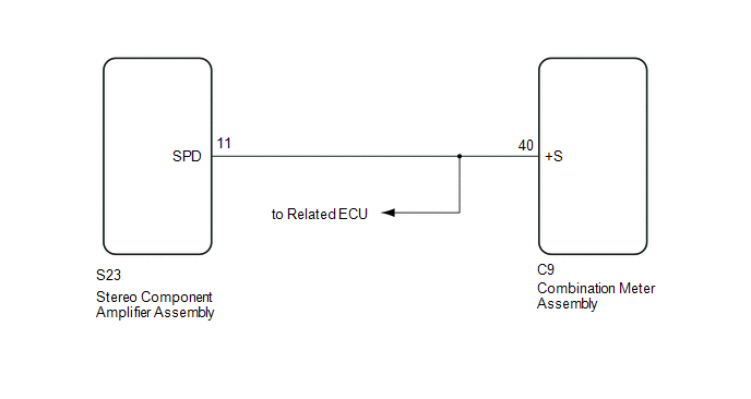
The stereo component amplifier assembly receives a vehicle speed signal from the combination meter assembly to control the ASL function.
HINT:
- A voltage of 12 V or 5 V is output from each ECU and then input to the combination meter assembly. The signal is changed to a pulse signal at the transistor in the combination meter assembly. Each ECU controls the respective systems based on the pulse signal.
- If a short occurs in any of the ECUs or in the wire harness connected to an ECU, related components will not operate normally.
WIRING DIAGRAM
PROCEDURE
|
1. |
INSPECT COMBINATION METER ASSEMBLY (OUTPUT WAVEFORM) |
|
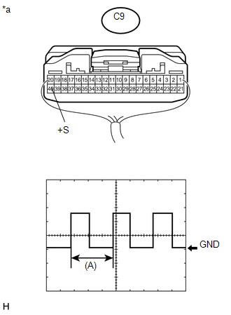
(a) Check the output waveform. (1) Remove the combination meter assembly with the connector(s) still connected. (2) Connect an oscilloscope to terminal C9-40 (+S) and body ground. (3) Turn the ignition switch to ON. (4) Turn a wheel slowly. (5) Check the signal waveform according to the condition(s) in the table below.
OK: The waveform is similar to that shown in the illustration. HINT: When the system is functioning normally, one wheel revolution generates 4 pulses. As the vehicle speed increases, the width indicated by (A) in the illustration narrows. Text in Illustration
|
|
| NG | .gif) |
GO TO METER / GAUGE SYSTEM |
|
.gif)
|
2. |
CHECK HARNESS AND CONNECTOR (STEREO COMPONENT AMPLIFIER ASSEMBLY - COMBINATION METER ASSEMBLY) |
(a) Disconnect the S23 stereo component amplifier assembly connector.
(b) Disconnect the C9 combination meter assembly connector.
(c) Measure the resistance according to the value(s) in the table below.
Standard Resistance:
|
Tester Connection |
Condition |
Specified Condition |
|---|---|---|
|
S23-11 (SPD) - C9-40 (+S) |
Always |
Below 1 Ω |
| OK | |
PROCEED TO NEXT SUSPECTED AREA SHOWN IN PROBLEM SYMPTOMS TABLE |
| NG | |
REPAIR OR REPLACE HARNESS OR CONNECTOR |
 AVC-LAN Circuit
DESCRIPTION
Each unit of the navigation system connected to the AVC-LAN (communication bus)
transfers the switch signals using the AVC-LAN.
If a short to +B or short to ground occurs in the AVC-LA ...
 Microphone Circuit between Microphone and Radio Receiver
DESCRIPTION
The navigation receiver assembly and telephone microphone assembly are connected
to each other using the microphone connection detection signal lines.
Using this circuit, the navigatio ...
Other materials:
Installation
INSTALLATION
PROCEDURE
1. INSTALL REAR DOOR GLASS SUB-ASSEMBLY
(a) Clean and shape the contact surface of the vehicle body.
Text in Illustration
*a
Adhesive
*b
Vehicle Body
(1) Using a ...
Communication Malfunction between ECUs Connected by LIN (B2785)
DESCRIPTION
The certification ECU (smart key ECU assembly) monitors communication between
all the ECUs connected to the certification bus lines. When the certification ECU
(smart key ECU assembly) detects errors in communication with all the ECUs connected
to the certification bus lines at a ...
Overhead console (Access Cab and Double Cab models)
The overhead console is useful for temporarily storing sunglasses and similar
small items.
Pull the lid down while pushing the knob.
CAUTION
■Caution while driving
Keep the overhead console closed.
Injuries may result in the event of an accident or sudden braking.
■Items unsuit ...
