Toyota Tacoma (2015-2018) Service Manual: Lost Communication with Meter (B1324)
DESCRIPTION
This DTC is stored when a communication error occurs between the navigation receiver assembly and combination meter assembly.
|
DTC No. |
DTC Detection Condition |
Trouble Area |
|---|---|---|
|
B1324 |
After the navigation receiver assembly receives a registration information signal, which is sent by the combination meter assembly when the ignition switch is ACC, 1 or more times, the navigation receiver assembly cannot receive the signal for 30 seconds or more. |
|
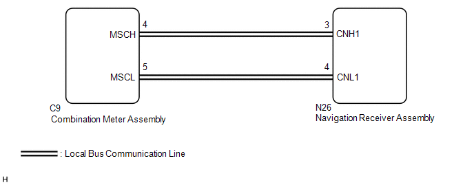
WIRING DIAGRAM
PROCEDURE
|
1. |
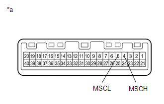
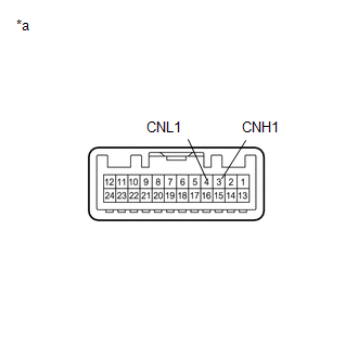
CHECK HARNESS AND CONNECTOR (NAVIGATION RECEIVER ASSEMBLY - COMBINATION METER ASSEMBLY) |
(a) Disconnect the N26 navigation receiver assembly connector.
(b) Disconnect the C9 combination meter assembly connector.
(c) Measure the resistance according to the value(s) in the table below.
Standard Resistance:
|
Tester Connection |
Condition |
Specified Condition |
|---|---|---|
|
N26-3 (CNH1) - C9-4 (MSCH) |
Always |
Below 1 Ω |
|
N26-4 (CNL1) - C9-5 (MSCL) |
Always |
Below 1 Ω |
|
N26-3 (CNH1) - Body ground |
Always |
10 kΩ or higher |
|
N26-4 (CNL1) - Body ground |
Always |
10 kΩ or higher |
|
N26-3 (CNH1) - N26-4 (CNL1) |
Always |
10 kΩ or higher |
(d) Measure the voltage according to the value(s) in the table below.
Standard Voltage:
|
Tester Connection |
Condition |
Specified Condition |
|---|---|---|
|
N26-3 (CNH1) - Body ground |
Always |
Below 1 V |
|
N26-4 (CNL1) - Body ground |
Always |
Below 1 V |
| NG | .gif) |
REPAIR OR REPLACE HARNESS OR CONNECTOR |
|
.gif)
|
2. |
INSPECT COMBINATION METER ASSEMBLY |
(a) Remove the combination meter assembly (See page
.gif) ).
).
|
(b) Measure the resistance according to the value(s) in the table below. Standard Resistance:
|
|
| NG | |
REPLACE COMBINATION METER ASSEMBLY |
|
|
3. |
INSPECT NAVIGATION RECEIVER ASSEMBLY |
(a) Remove the navigation receiver assembly (See page
).
|
(b) Measure the resistance according to the value(s) in the table below. Standard Resistance:
|
|
| NG | |
REPLACE NAVIGATION RECEIVER ASSEMBLY |
|
|
4. |
REPLACE COMBINATION METER ASSEMBLY |
(a) Replace the combination meter assembly with a new or known good one (See
page ).
(b) Clear the DTCs (See page ).
(c) Recheck for DTCs and check that no DTCs are output.
OK:
No DTCs are output.
| NG | |
REPLACE NAVIGATION RECEIVER ASSEMBLY |
|
|
5. |
CHECK METER / GAUGE SYSTEM |
(a) Turn the ignition switch to ON and wait 30 seconds.
(b) Operate the steering pad switch assembly and check that the audio tab is displayed on the multi-information display in the combination meter assembly and the audio system can be operated normally.
OK:
Audio system returns to normal.
| OK | |
END |
| NG | |
REPLACE NAVIGATION RECEIVER ASSEMBLY |
 Diagnostic Trouble Code Chart
DIAGNOSTIC TROUBLE CODE CHART
Navigation System
DTC Code
Detection Item
See page
B1324
Lost Communication with Meter
...
 LVDS Signal Malfunction (from Extension Module) (B1532,B156C)
DESCRIPTION
DTC Code
DTC Detection Condition
Trouble Area
B1532
When one of the conditions below is met:
Video signal (digit ...
Other materials:
TC and CG Terminal Circuit
DESCRIPTION
The DLC3 circuit enables reading of Diagnostic Trouble Codes (DTCs) with no Techstream
by connecting terminals TC and CG of the DLC3 connector.
Stored DTCs are displayed in blinking patterns of the CRUISE MAIN indicator light
located on the combination meter.
WIRING DIAGRAM
HIN ...
Removal
REMOVAL
CAUTION / NOTICE / HINT
HINT:
If the bumper is damaged, there is a possibility that the installation area of
the blind spot monitor sensor may be deformed and the blind spot monitor system
may not operate correctly, so visually inspect the blind spot monitor sensor installation
area ...
On-vehicle Inspection
ON-VEHICLE INSPECTION
PROCEDURE
1. INSPECT CURTAIN SHIELD AIRBAG ASSEMBLY (for Vehicle not Involved in Collision)
(a) Perform a diagnostic system check (See page
).
(b) With the curtain shield airbag assembly installed on the vehicle,
perform a visual check. If there are any def ...
