Toyota Tacoma (2015-2018) Service Manual: LVDS Signal Malfunction (from Extension Module) (B1532,B156C)
DESCRIPTION
|
DTC Code |
DTC Detection Condition |
Trouble Area |
|---|---|---|
|
B1532 |
When one of the conditions below is met:
|
|
|
B156C |
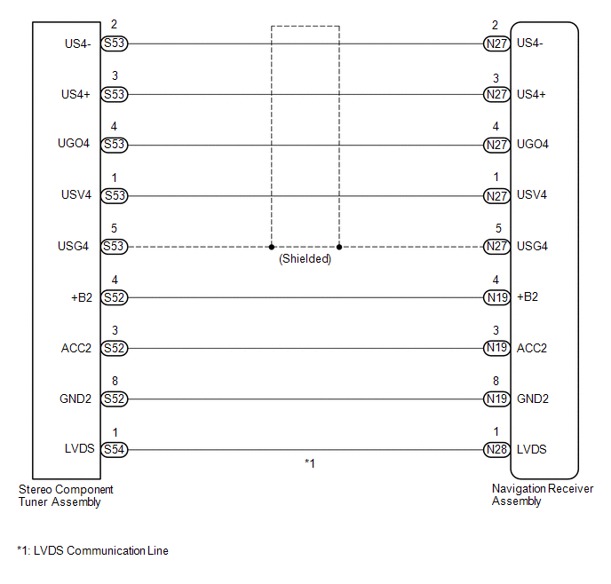
WIRING DIAGRAM
CAUTION / NOTICE / HINT
NOTICE:
After replacing the stereo component tuner assembly of vehicles subscribed to pay-type satellite radio broadcasts, XM radio ID registration is necessary. (w/ SDARS System)
PROCEDURE
|
1. |
CHECK DTC |
(a) Clear the DTCs (See page .gif) ).
).
(b) Check for DTCs (See page ).
OK:
No DTCs are output.
| OK | .gif) |
USE SIMULATION METHOD TO CHECK |
|
.gif)
|
2. |
CHECK HARNESS AND CONNECTOR (NAVIGATION RECEIVER ASSEMBLY - STEREO COMPONENT TUNER ASSEMBLY) |
(a) Disconnect the N19, N27 and N28 navigation receiver assembly connectors.
(b) Disconnect the S52, S53 and S54 stereo component tuner assembly connectors.
(c) Measure the resistance according to the value(s) in the table below.
Standard Resistance:
|
Tester Connection |
Condition |
Specified Condition |
|---|---|---|
|
N27-1 (USV4) - S53-1 (USV4) |
Always |
Below 1 Ω |
|
N27-2 (US4-) - S53-2 (US4-) |
Always |
Below 1 Ω |
|
N27-3 (US4+) - S53-3 (US4+) |
Always |
Below 1 Ω |
|
N27-4 (UGO4) - S53-4 (UGO4) |
Always |
Below 1 Ω |
|
N27-5 (USG4) - S53-5 (USG4) |
Always |
Below 1 Ω |
|
N19-4 (+B2) - S52-4 (+B) |
Always |
Below 1 Ω |
|
N19-3 (ACC2) - S52-3 (ACC2) |
Always |
Below 1 Ω |
|
N19-8 (GND2) - S52-8 (GND2) |
Always |
Below 1 Ω |
|
N28-1 (LVDS) - S54-1 (LVDS) |
Always |
Below 1 Ω |
|
N27-1 (USV4) - Body ground |
Always |
10 kΩ or higher |
|
N27-2 (US4-) - Body ground |
Always |
10 kΩ or higher |
|
N27-3 (US4+) - Body ground |
Always |
10 kΩ or higher |
|
N27-4 (UGO4) - Body ground |
Always |
10 kΩ or higher |
|
N27-5 (USG4) - Body ground |
Always |
10 kΩ or higher |
|
N19-4 (+B2) - Body ground |
Always |
10 kΩ or higher |
|
N19-3 (ACC2) - Body ground |
Always |
10 kΩ or higher |
|
N19-8 (GND2) - Body ground |
Always |
10 kΩ or higher |
|
N28-1 (LVDS) - Body ground |
Always |
10 kΩ or higher |
| NG | |
REPAIR OR REPLACE HARNESS OR CONNECTOR |
|
|
3. |
CHECK NO. 1 NAVIGATION WIRE |
(a) Replace the No. 1 navigation wire with a known good one (See page
).
(b) Clear the DTCs (See page ).
(c) Check for DTCs (See page ).
OK:
No DTCs are output.
| OK | |
END (NO. 1 NAVIGATION WIRE WAS DEFECTIVE) |
|
|
4. |
CHECK STEREO COMPONENT TUNER ASSEMBLY |
(a) Replace the stereo component tuner assembly with a known good one (See page
).
(b) Clear the DTCs (See page ).
(c) Check for DTCs (See page ).
OK:
No DTCs are output.
| OK | |
END (STEREO COMPONENT TUNER ASSEMBLY IS DEFECTIVE) |
| NG | |
REPLACE NAVIGATION RECEIVER ASSEMBLY |
 Lost Communication with Meter (B1324)
DESCRIPTION
This DTC is stored when a communication error occurs between the navigation receiver
assembly and combination meter assembly.
DTC No.
DTC Detection Condition
...
 HD Radio Tuner Malfunction (B1551,B15A0,B15AD,B15B0,B15B3,B15B4,B15B7)
DESCRIPTION
These DTCs are stored when a malfunction occurs in the navigation receiver assembly.
DTC No.
DTC Detection Condition
Trouble Area
B1551
...
Other materials:
Front Differential Oil Temperature Sensor Circuit High (P17C8)
DESCRIPTION
This DTC is output when a short to B+ or open circuit in the oil temperature
sensor is detected.
DTC No.
Detection Item
DTC Detection Condition
Trouble Area
P17C8
Front Differential Oil Temperature Sensor Circuit ...
Radio Antenna Cord
Components
COMPONENTS
ILLUSTRATION
Removal
REMOVAL
PROCEDURE
1. REMOVE INSTRUMENT PANEL SUB-ASSEMBLY
(See page )
2. REMOVE ANTENNA CORD SUB-ASSEMBLY
(a) Disengage the 4 clamps to remove the antenna cord sub-assembly.
Installation
INSTALLATION
PROCEDURE
1. INSTALL ANTENNA COR ...
Problem Symptoms Table
PROBLEM SYMPTOMS TABLE
HINT:
Use the table below to help determine the cause of problem symptoms. If multiple
suspected areas are listed, the potential causes of the symptoms are listed in order
of probability in the "Suspected Area" column of the table. Check each symptom by
check ...
