Toyota Tacoma (2015-2018) Service Manual: Clutch Start Cancel Switch
Inspection
INSPECTION
PROCEDURE
1. INSPECT CLUTCH START CANCEL SWITCH ASSEMBLY
|
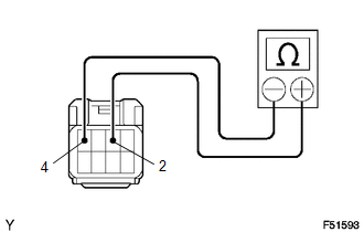
(a) Using an ohmmeter, check that there is resistance between terminals 2 and 4. Standard: 10 kΩ or higher If the result is not as specified, replace the clutch start cancel switch. |
|
|
(b) Connect the positive (+) lead from the battery to terminal 3 and connect negative (-) lead to terminal 1. |
|
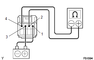
(c) Using an ohmmeter, check that there is resistance between terminals 2 and 4.
Standard:
10 kΩ or higher
If the result is not as specified, replace the clutch start cancel switch.
|
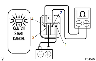
(d) Check that the indicator light comes on and there is resistance between terminals 2 and 4 when the switch is pressed. Standard: Below 1 Ω If the result is not as specified, replace the clutch start cancel switch. |
|
|
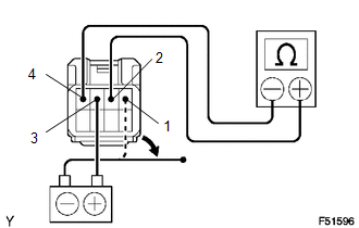
(e) Using an ohmmeter, check that there is resistance between terminals 2 and 4 when the battery lead is disconnected. Standard: 10 kΩ or higher If the result is not as specified, replace the clutch start cancel switch. |
|
 Clutch Release Cylinder(for Rc62f)
Components
COMPONENTS
ILLUSTRATION
Disassembly
DISASSEMBLY
PROCEDURE
1. REMOVE CLUTCH RELEASE CYLINDER KIT
(a) Remove the boot from the cylinder body.
(b) Remove the push rod from the bo ...
 Clutch System
...
Other materials:
Display does not Dim when Light Control Switch is Turned ON
PROCEDURE
1.
CHECK IMAGE QUALITY SETTING
(a) Display the "Display" screen.
(b) Turn the light control switch to the tail or head position.
(c) Check if "Day Mode" on the display adjustment screen is on.
OK:
"Day Mode" setting is of ...
Installation
INSTALLATION
PROCEDURE
1. INSTALL TRANSFER POSITION SWITCH (for 4WD)
Click here
2. INSTALL ENGINE SWITCH
Click here
3. INSTALL AIR CONDITIONING CONTROL ASSEMBLY
(a) Connect the connectors.
(b) Engage the 8 clips to install the air conditioning control assembly.
4. INSTALL RADIO AND DISP ...
Registration
REGISTRATION
PROCEDURE
1. DESCRIPTION OF CODE REGISTRATION
HINT:
Registering an ID code enables the entry and start function, wireless
door lock control function and engine immobiliser function to be operated.
Code registration is needed when the certification ECU (smart key E ...
