Toyota Tacoma (2015-2018) Service Manual: Installation
INSTALLATION
PROCEDURE
1. INSTALL CAMSHAFT TIMING OIL CONTROL SOLENOID ASSEMBLY (for Intake Side of Bank 1)
|
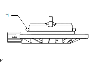
(a) Apply engine oil to a new O-ring and install it to the camshaft timing oil control solenoid assembly in the locations shown in the illustration. Text in Illustration
|
|
(b) Install the camshaft timing oil control solenoid assembly to the timing chain cover assembly with 2 new bolts.
Torque:
10 N·m {102 kgf·cm, 7 ft·lbf}
NOTICE:
Be careful that the O-ring is not jammed.
(c) Connect the connector to the camshaft timing oil control solenoid assembly.
2. INSTALL CAMSHAFT TIMING OIL CONTROL SOLENOID ASSEMBLY (for Exhaust Side of Bank 1)
|
(a) Apply engine oil to a new O-ring and install it to the camshaft timing oil control solenoid assembly in the locations shown in the illustration. Text in Illustration
|
|
(b) Install the camshaft timing oil control solenoid assembly to the timing chain cover assembly with 2 new bolts.
Torque:
10 N·m {102 kgf·cm, 7 ft·lbf}
NOTICE:
Be careful that the O-ring is not jammed.
(c) Connect the connector to the camshaft timing oil control solenoid assembly.
3. INSTALL CAMSHAFT TIMING OIL CONTROL SOLENOID ASSEMBLY (for Intake Side of Bank 2)
|
(a) Apply engine oil to a new O-ring and install it to the camshaft timing oil control solenoid assembly in the locations shown in the illustration. Text in Illustration
|
|
(b) Install the camshaft timing oil control solenoid assembly to the timing chain cover assembly with 2 new bolts.
Torque:
10 N·m {102 kgf·cm, 7 ft·lbf}
NOTICE:
Be careful that the O-ring is not jammed.
(c) Connect the connector to the camshaft timing oil control solenoid assembly.
4. INSTALL CAMSHAFT TIMING OIL CONTROL SOLENOID ASSEMBLY (for Exhaust Side of Bank 2)
|
(a) Apply engine oil to a new O-ring and install it to the camshaft timing oil control solenoid assembly in the locations shown in the illustration. Text in Illustration
|
|
(b) Install the camshaft timing oil control solenoid assembly to the timing chain cover assembly with 2 new bolts.
Torque:
10 N·m {102 kgf·cm, 7 ft·lbf}
NOTICE:
Be careful that the O-ring is not jammed.
(c) Connect the connector to the camshaft timing oil control solenoid assembly.
5. INSTALL THROTTLE BODY BRACKET
(a) Install the throttle body bracket to the intake air surge tank assembly and timing chain cover assembly with the 2 bolts.
Torque:
21 N·m {214 kgf·cm, 15 ft·lbf}
6. INSTALL ENGINE OIL LEVEL DIPSTICK GUIDE
(a) Apply engine oil to a new O-ring and install it to the engine oil level dipstick guide.
(b) Install the engine oil level dipstick guide to the timing chain cover assembly and oil pan sub-assembly with the bolt.
Torque:
10 N·m {102 kgf·cm, 7 ft·lbf}
(c) Engage the clamp to install the wire harness.
(d) Install the engine oil level dipstick.
7. INSTALL AIR CLEANER CAP AND HOSE
.gif)
8. INSTALL V-BANK COVER SUB-ASSEMBLY
9. INSTALL FRONT FENDER SEAL RH
HINT:
Use the same procedure as for the LH side (See page
).
 Removal
REMOVAL
PROCEDURE
1. REMOVE FRONT FENDER SEAL RH
HINT:
Use the same procedure as for the LH side (See page
).
2. REMOVE V-BANK COVER SUB-ASSEMBLY
3. REMOVE AIR CLEANER CAP AND HOSE
4. ...

Other materials:
Transmitter ID not Registered (C2171/71)
DESCRIPTION
The IDs of each tire pressure warning valve and transmitter are registered to
the tire pressure warning ECU and receiver.
When the ECU detects that a transmitter ID code is not registered in the ECU,
this DTC is stored.
DTC No.
Detection Item
DTC D ...
Cruise Control Switch Circuit
DESCRIPTION
This circuit sends signals to the ECM depending on the cruise control main switch
condition.
The battery supplies the positive (+) battery voltage to the cruise control main
switch. Then terminal CCS of the ECM receives the voltage as the signal according
to the switch condition. ...
Problem Symptoms Table
PROBLEM SYMPTOMS TABLE
HINT:
Use the table below to help determine the cause of problem symptoms.
If multiple suspected areas are listed, the potential causes of the symptoms
are listed in order of probability in the "Suspected Area" column of the
table. Check each sy ...
