Toyota Tacoma (2015-2018) Service Manual: Removal
REMOVAL
PROCEDURE
1. REMOVE FRONT FENDER SEAL RH
HINT:
Use the same procedure as for the LH side (See page
.gif) ).
).
2. REMOVE V-BANK COVER SUB-ASSEMBLY
3. REMOVE AIR CLEANER CAP AND HOSE
4. REMOVE ENGINE OIL LEVEL DIPSTICK GUIDE
(a) Remove the engine oil level dipstick.
|
(b) Disengage the clamp to separate the wire harness. |
|
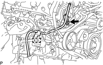
(c) Remove the bolt and engine oil level dipstick guide from the timing chain cover assembly and oil pan sub-assembly.
(d) Remove the O-ring from the engine oil level dipstick guide.
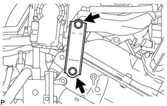
5. REMOVE THROTTLE BODY BRACKET
|
(a) Remove the 2 bolts and throttle body bracket from the intake air surge tank assembly and timing chain cover assembly. |
|
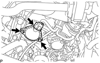
6. REMOVE CAMSHAFT TIMING OIL CONTROL SOLENOID ASSEMBLY (for Intake Side of Bank 1)
|
(a) Disconnect the connector from the camshaft timing oil control solenoid assembly. |
|
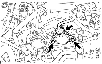
(b) Remove the 2 bolts and camshaft timing oil control solenoid assembly from the timing chain cover assembly.
(c) Remove the O-ring from the camshaft timing oil control solenoid assembly.
HINT:
- Make sure to remove the O-ring completely, as the O-ring may remain on the timing chain cover assembly side.
- Do not drop the O-ring into the timing chain cover assembly.
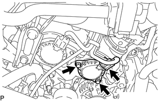
7. REMOVE CAMSHAFT TIMING OIL CONTROL SOLENOID ASSEMBLY (for Exhaust Side of Bank 1)
|
(a) Disconnect the connector from the camshaft timing oil control solenoid assembly. |
|
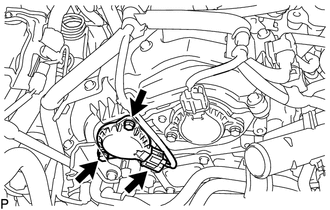
(b) Remove the 2 bolts and camshaft timing oil control solenoid assembly from the timing chain cover assembly.
(c) Remove the O-ring from the camshaft timing oil control solenoid assembly.
HINT:
- Make sure to remove the O-ring completely, as the O-ring may remain on the timing chain cover assembly side.
- Do not drop the O-ring into the timing chain cover assembly.
8. REMOVE CAMSHAFT TIMING OIL CONTROL SOLENOID ASSEMBLY (for Intake Side of Bank 2)
|
(a) Disconnect the connector from the camshaft timing oil control solenoid assembly. |
|
(b) Remove the 2 bolts and camshaft timing oil control solenoid assembly from the timing chain cover assembly.
(c) Remove the O-ring from the camshaft timing oil control solenoid assembly.
HINT:
- Make sure to remove the O-ring completely, as the O-ring may remain on the timing chain cover assembly side.
- Do not drop the O-ring into the timing chain cover assembly.
9. REMOVE CAMSHAFT TIMING OIL CONTROL SOLENOID ASSEMBLY (for Exhaust Side of Bank 2)
|
(a) Disconnect the connector from the camshaft timing oil control solenoid assembly. |
|
(b) Remove the 2 bolts and camshaft timing oil control solenoid assembly from the timing chain cover assembly.
(c) Remove the O-ring from the camshaft timing oil control solenoid assembly.
HINT:
- Make sure to remove the O-ring completely, as the O-ring may remain on the timing chain cover assembly side.
- Do not drop the O-ring into the timing chain cover assembly.
 Inspection
INSPECTION
PROCEDURE
1. INSPECT CAMSHAFT TIMING OIL CONTROL SOLENOID ASSEMBLY
(a) Check the operation.
(1) Apply battery voltage between the terminals and check that the plunger
ope ...
 Installation
INSTALLATION
PROCEDURE
1. INSTALL CAMSHAFT TIMING OIL CONTROL SOLENOID ASSEMBLY (for Intake Side of
Bank 1)
(a) Apply engine oil to a new O-ring and install it to the camshaft timing
...
Other materials:
Terminals Of Ecu
TERMINALS OF ECU
1. CHECK POWER WINDOW REGULATOR MASTER SWITCH ASSEMBLY
(a) for Double Cab
(1) Disconnect the P18 power window regulator master switch assembly connector.
(2) Measure the voltage and resistance according to the value(s) in the table
below.
HINT:
Measure the values on the wi ...
SM Solenoid Circuit (C1225,C1468,C1469,C146A,C146B)
DESCRIPTION
These solenoids turn on when signals are received from the skid control ECU (brake
actuator assembly) and they control the pressure acting on the wheel cylinders to
control the braking force.
DTC No.
Detection Item
DTC Detection Condition
...
Door Unlock Detection Switch Circuit
DESCRIPTION
The main body ECU (multiplex network body ECU) detects the condition of each
door unlock detection switch.
WIRING DIAGRAM
CAUTION / NOTICE / HINT
NOTICE:
If the main body ECU (multiplex network body ECU) is replaced, refer to Registration
(See page ).*1
*1: w/ Smart K ...
