Toyota Tacoma (2015-2018) Service Manual: Installation
INSTALLATION
PROCEDURE
1. INSTALL FRONT BUMPER ASSEMBLY
(a) w/ Fog Light:
(1) Connect the 2 connectors.
(b) Engage the 3 claws and guide to install the front bumper assembly.
(c) Remove the protective tape.
(d) Install the 6 clips.
(e) Engage the clamp.
(f) Connect the connector.
(g) Install the 2 bolts and 4 screws.
Torque:
Bolt :
5.0 N┬Ęm {51 kgf┬Ęcm, 44 in┬Ęlbf}
Screw :
2.8 N┬Ęm {29 kgf┬Ęcm, 25 in┬Ęlbf}
|
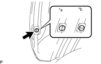
(h) Install the pin hold clip as shown in the illustration. NOTICE: Insert the pin hold clip with the slot aligned vertically. Do not rotate the clip after inserting it. After installation, confirm that the slot is aligned vertically. HINT: Use the same procedure for the RH side and LH side. |
|
(i) w/o Over Fender:
(1) Install the screw.
HINT:
Use the same procedure for the RH side and LH side.
2. INSTALL RADIATOR GRILLE
Click here .gif)
3. INSTALL FRONT NO. 1 WHEEL OPENING EXTENSION PAD (w/ Front Spoiler)
(a) Install front No. 1 wheel opening extension pad with 9 screws.
4. INSTALL FRONT FENDER WHEEL OPENING MOULDING (w/ Over Fender)
Click here
5. INSTALL FRONT FENDER MUDGUARD (w/ Mudguard)
Click here
6. ADJUST MILLIMETER WAVE RADAR SENSOR ASSEMBLY
Click here
 Removal
REMOVAL
PROCEDURE
1. REMOVE FRONT FENDER MUDGUARD (w/ Mudguard)
Click here
2. REMOVE FRONT FENDER WHEEL OPENING MOULDING (w/ Over Fender)
Click here
3. REMOVE FRONT NO. 1 WHEEL OPENING EXTEN ...

Other materials:
Disassembly
DISASSEMBLY
PROCEDURE
1. REMOVE HOOD BULGE ASSEMBLY (w/ Hood Bulge)
(a) Remove the 4 nuts.
(b) Disengage the clip from back side of the hood panel to remove the hood bulge
assembly together with the air intake guide.
2. REMOVE NO. 2 HOOD BU ...
Replacement
REPLACEMENT
PROCEDURE
1. REPLACE AUTOMATIC TRANSMISSION FLUID
(a) Lift the vehicle. [*1]
NOTICE:
Set the vehicle on a lift so that the vehicle is kept level when it is lifted
up (make sure that the tilt angle from the front to rear of the vehicle is within
+/-1┬░).
(b) Remove th ...
System Diagram
SYSTEM DIAGRAM
...
