Toyota Tacoma (2015-2018) Service Manual: Installation
INSTALLATION
PROCEDURE
1. INSTALL CENTER STOP LIGHT ASSEMBLY (for Bulb Type Stop Light)
(a) Install the 3 center stop light bulbs to the 3 center stop light sockets.
|
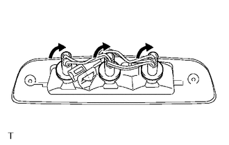
(b) Turn the 3 center stop light sockets with 3 center stop light bulbs in the direction indicated by the arrow shown in the illustration to install them. |
|
(c) Connect the connector.
(d) Install the center stop light assembly with the 2 screws.
(e) Remove the protective tape.
2. INSTALL CENTER STOP LIGHT ASSEMBLY (for LED Type Stop Light)
(a) Connect the connector.
|
(b) Engage the 2 clips to install the center stop light assembly. |
|
.png)
(c) Install the 2 nuts.
Torque:
3.6 N·m {36 kgf·cm, 31 in·lbf}
(d) Remove the protective tape.
3. CONNECT ROOF HEADLINING ASSEMBLY (for LED Type Stop Light)
- for Double Cab:
(See page
.gif) )
) - for Access Cab:
(See page
)
 Removal
REMOVAL
PROCEDURE
1. REMOVE ROOF HEADLINING ASSEMBLY (for LED Type Stop Light)
for Double Cab:
(See page
)
for Access Cab:
(See page
)
2. REMOVE CENTER STOP ...
 Interior Illumination Light
Components
COMPONENTS
ILLUSTRATION
Removal
REMOVAL
PROCEDURE
1. REMOVE INSTRUMENT PANEL LOWER CENTER FINISH PANEL
(See page )
2. REMOVE NO. 1 INTERIOR ILLUMINATION LIGHT ASSEMBLY
...
Other materials:
Dtc Check / Clear
DTC CHECK / CLEAR
1. CHECK FOR TRANSPONDER KEY ECU ASSEMBLY DTC
(a) Connect the Techstream to the DLC3.
(b) Turn the ignition switch to ON.
(c) Turn the Techstream on.
(d) Enter the following menus: Body Electrical / Immobiliser / Trouble Codes.
(e) Check the details of the DTC(s) (See page
...
How To Proceed With Troubleshooting
CAUTION / NOTICE / HINT
HINT:
Use the following procedure listed to troubleshoot the differential
system (w/ Differential Lock).
*: Use the Techstream.
PROCEDURE
1.
VEHICLE BROUGHT TO WORKSHOP
NEXT
...
Test Mode Procedure
TEST MODE PROCEDURE
1. TEST MODE (SIGNAL CHECK MODE) PROCEDURE
HINT:
When entering test mode (signal check mode), the tire pressure warning
ECU and receiver stores all the test mode (signal check mode) DTCs first.
After the tire pressure warning ECU and receiver completes the signa ...
