Toyota Tacoma (2015-2018) Service Manual: Installation
INSTALLATION
PROCEDURE
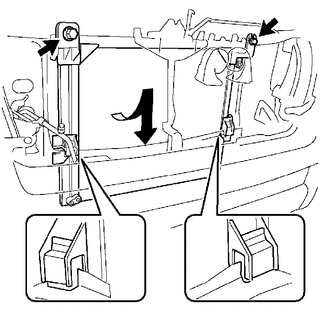
1. INSTALL COOLER CONDENSER ASSEMBLY
(a) Engage the 2 claws to install the 2 condenser upper brackets.
(b) Engage the 2 claws to install the 2 condenser lower brackets.
|
(c) Lift the cooler condenser assembly up from the rear side of the vehicle, and install the condenser lower brackets onto the upper part of the radiator lower supports with the 2 bolts. Torque: 9.0 N·m {92 kgf·cm, 80 in·lbf} |
|
2. INSTALL AIR CONDITIONING TUBE ASSEMBLY
(a) Remove the vinyl tape from the air conditioning tube assembly and connecting part of the cooler condenser assembly.
(b) Apply sufficient compressor oil to a new O-ring and fitting surface of the cooler condenser assembly.
Compressor oil:
PSD1 or equivalent
(c) Install the O-ring to the air conditioning tube assembly.
(d) Install the air conditioning tube assembly to the cooler condenser assembly with the bolt.
Torque:
9.8 N·m {100 kgf·cm, 87 in·lbf}
3. INSTALL DISCHARGE HOSE SUB-ASSEMBLY
(a) Remove the vinyl tape from the discharge hose sub-assembly and connecting part of the cooler condenser assembly.
(b) Apply sufficient compressor oil to a new O-ring and fitting surface of the cooler condenser assembly.
Compressor oil:
PSD1 or equivalent
(c) Install the O-ring to the discharge hose sub-assembly.
(d) Install the discharge hose sub-assembly to the cooler condenser assembly with the bolt.
Torque:
9.8 N·m {100 kgf·cm, 87 in·lbf}
4. INSTALL RADIATOR ASSEMBLY (for 2TR-FE)
Click here .gif)
5. INSTALL RADIATOR ASSEMBLY (for 2GR-FKS)
Click here
6. CONNECT CABLE TO NEGATIVE BATTERY TERMINAL
Torque:
5.4 N·m {55 kgf·cm, 48 in·lbf}
NOTICE:
When disconnecting the cable, some systems need to be initialized after the cable is reconnected.
Click here
7. CHARGE AIR CONDITIONING SYSTEM WITH REFRIGERANT
Click here
8. WARM UP ENGINE
Click here
9. INSPECT FOR REFRIGERANT LEAK
Click here
 Removal
REMOVAL
PROCEDURE
1. PRECAUTION
NOTICE:
After turning the ignition switch off, waiting time may be required before disconnecting
the cable from the negative (-) battery terminal. Therefore, make ...
 Front Blower Motor
Inspection
INSPECTION
PROCEDURE
1. INSPECT BLOWER MOTOR
(a) Inspect the blower motor.
(1) Connect the positive (+) lead from to terminal 1 and negative (-)
lead to terminal 2, ...
Other materials:
On-vehicle Inspection
ON-VEHICLE INSPECTION
PROCEDURE
1. INSPECT BRAKE PEDAL HEIGHT
(a) Check the brake pedal height.
Pedal height from dash panel:
Type
Pedal Height
Automatic transmission
164.4 to 174.4 mm (6.473 to 6.866 in.)
Manual transmission ...
Engine does not Start but Initial Combustion Occurs
DESCRIPTION
If the key ID codes of the key and transponder key ECU assembly match, the engine
immobiliser system is unset and the engine start permission signal is sent to the
ECM. When the ID codes of the transponder key ECU assembly and ECM match, the engine
starts.
WIRING DIAGRAM
CAUTI ...
Data List / Active Test
DATA LIST / ACTIVE TEST
DATA LIST
HINT:
Using the Techstream to read the Data List allows the values or states of switches,
sensors, actuators and other items to be read without removing any parts. This non-intrusive
inspection can be very useful because intermittent conditions or signals may ...
