Toyota Tacoma (2015-2018) Service Manual: Engine does not Start but Initial Combustion Occurs
DESCRIPTION
If the key ID codes of the key and transponder key ECU assembly match, the engine immobiliser system is unset and the engine start permission signal is sent to the ECM. When the ID codes of the transponder key ECU assembly and ECM match, the engine starts.
WIRING DIAGRAM
.png)
CAUTION / NOTICE / HINT
NOTICE:
If the transponder key ECU assembly or ECM is replaced, refer to Registration
(See page .gif) ).
).
PROCEDURE
|
1. |
CLEAR DTC |
(a) Clear the DTCs (See page ).
|
.gif)
|
2. |
CHECK FOR DTC |
(a) Check for DTCs (See page ).
|
Result |
Proceed to |
|---|---|
|
DTCs are not output |
A |
|
DTCs are output |
B |
| B | .gif) |
GO TO DIAGNOSTIC TROUBLE CODE CHART |
|
|
3. |
READ VALUE USING TECHSTREAM (IMMOBILISER FUEL CUT) |
(a) Connect the Techstream to the DLC3.
(b) Turn the ignition switch to ON.
(c) Turn the Techstream on.
(d) Enter the following menus: Powertrain / Engine and ECT or Engine / Data List.
(e) Read the Data List according to the display on the Techstream.
Engine and ECT (for 2TR-FE)|
Tester Display |
Measurement Item/Range |
Normal Condition |
Diagnostic Note |
|---|---|---|---|
|
Immobiliser Fuel Cut |
Status of immobiliser fuel cut / ON or OFF |
- |
- |
|
Tester Display |
Measurement Item/Range |
Normal Condition |
Diagnostic Note |
|---|---|---|---|
|
Immobiliser Fuel Cut |
Status of immobiliser fuel cut / ON or OFF |
- |
- |
OK:
OFF is displayed after the ignition switch is turned ON.
Result|
Result |
Proceed to |
|---|---|
|
NG |
A |
|
OK (for 2TR-FE) |
B |
|
OK (for 2GR-FKS) |
C |
| B | |
GO TO SFI SYSTEM |
| C | |
GO TO SFI SYSTEM |
|
|
4. |
CHECK WHETHER ENGINE STARTS |
(a) Using a registered key, turn the ignition switch to ON.
(b) Check that the engine starts 5 seconds after the ignition switch was turned to ON.
OK:
Engine starts normally.
Result|
Result |
Proceed to |
|---|---|
|
NG (for 2TR-FE) |
A |
|
NG (for 2GR-FKS) |
B |
|
OK |
C |
| B | |
GO TO STEP 15 |
| C | |
USE SIMULATION METHOD TO CHECK |
|
|
5. |
CHECK ECM (TERMINAL IMI) |
(a) Using an oscilloscope, check the waveform.
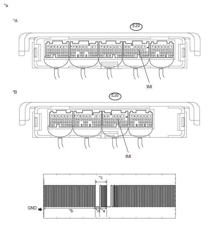 Text in Illustration
|
*A |
for Automatic Transmission |
*B |
for Manual Transmission |
|
*a |
Component with harness connected (ECM) |
*b |
Waveform 1 |
|
*c |
Waveform 2 |
*d |
Approximately 160 ms |
|
*e |
Approximately 270 ms |
- |
- |
Measurement Condition:
|
Tester Connection |
Condition |
Tool Setting |
Specified Condition |
|---|---|---|---|
|
E20-10 (IMI) - Body ground |
Within 3 seconds of starter operation and initial combustion, or within 3 seconds of ignition switch first being turned to ON after cable disconnected and reconnected to negative (-) battery terminal |
2 V/DIV., 500 ms./DIV. |
Pulse generation (See waveform) |
|
Result |
Proceed to |
|---|---|
|
Normal waveform |
A |
|
Waveform 1 not output, or has abnormal wavelength or shape |
B |
|
Waveform 2 not output, or has abnormal wavelength or shape |
C |
| B | |
GO TO STEP 12 |
| C | |
GO TO STEP 13 |
|
|
6. |
CHECK ECM (TERMINAL IMO) |
(a) Using an oscilloscope, check the waveform.
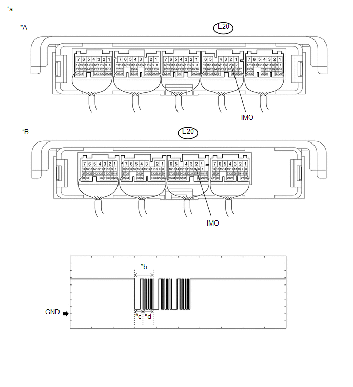 Text in Illustration
|
*A |
for Automatic Transmission |
*B |
for Manual Transmission |
|
*a |
Component with harness connected (ECM) |
*b |
Waveform |
|
*c |
Approximately 160 ms |
*d |
Approximately 270 ms |
Measurement Condition:
|
Tester Connection |
Condition |
Tool Setting |
Specified Condition |
|---|---|---|---|
|
E20-9 (IMO) - Body ground |
Within 3 seconds of starter operation and initial combustion, or within 3 seconds of ignition switch first being turned to ON after cable disconnected and reconnected to negative (-) battery terminal |
2 V/DIV., 500 ms./DIV. |
Pulse generation (See waveform) |
|
Result |
Proceed to |
|---|---|
|
Normal waveform |
A |
|
Waveform not output, or has abnormal wavelength or shape |
B |
| B | |
GO TO STEP 9 |
|
|
7. |
REGISTER ECU COMMUNICATION ID |
(a) Register the communication ID between the transponder key ECU assembly and
ECM (See page ).
|
|
8. |
CHECK WHETHER ENGINE STARTS |
(a) Using a registered key, turn the ignition switch to ON.
(b) Check that the engine starts 5 seconds after the ignition switch was turned to ON.
OK:
Engine starts normally.
| OK | |
END (REGISTERED COMMUNICATION ID WAS DEFECTIVE) |
| NG | |
GO TO STEP 13 |
|
9. |
REPLACE ECM |
(a) Temporarily replace the ECM with a new one (See page
).
|
|
10. |
REGISTER ECU COMMUNICATION ID |
(a) Register the ECU communication ID (See page
).
|
|
11. |
CHECK WHETHER ENGINE STARTS |
(a) Using a registered key, turn the ignition switch to ON.
(b) Check that the engine starts 5 seconds after the ignition switch was turned to ON.
OK:
Engine starts normally.
| OK | |
END (ECM WAS DEFECTIVE) |
| NG | |
GO TO SFI SYSTEM |
|
12. |
CHECK HARNESS AND CONNECTOR (TRANSPONDER KEY ECU ASSEMBLY - ECM) |
(a) Disconnect the T10 transponder key ECU assembly connector.
(b) Disconnect the E20 ECM connector.
(c) Measure the resistance according to the value(s) in the table below.
Standard Resistance:
|
Tester Connection |
Condition |
Specified Condition |
|---|---|---|
|
T10-13 (EFIO) - E20-10 (IMI) |
Always |
Below 1 Ω |
|
T10-13 (EFIO) or E20-10 (IMI) - Body ground |
Always |
10 kΩ or higher |
| NG | |
REPAIR OR REPLACE HARNESS OR CONNECTOR |
|
|
13. |
REPLACE TRANSPONDER KEY ECU ASSEMBLY |
(a) Replace the transponder key ECU assembly with a new one (See page
).
NOTICE:
Key ID code registration is necessary when replacing the transponder key ECU
assembly, refer to Registration (See page ).
|
|
14. |
CHECK WHETHER ENGINE STARTS |
(a) Using a registered key, turn the ignition switch to ON.
(b) Check that the engine starts 5 seconds after the ignition switch was turned to ON.
OK:
Engine starts normally.
| OK | |
END (TRANSPONDER KEY ECU ASSEMBLY WAS DEFECTIVE) |
| NG | |
GO TO SFI SYSTEM |
|
15. |
CHECK ECM (TERMINAL IMI) |
(a) Using an oscilloscope, check the waveform.
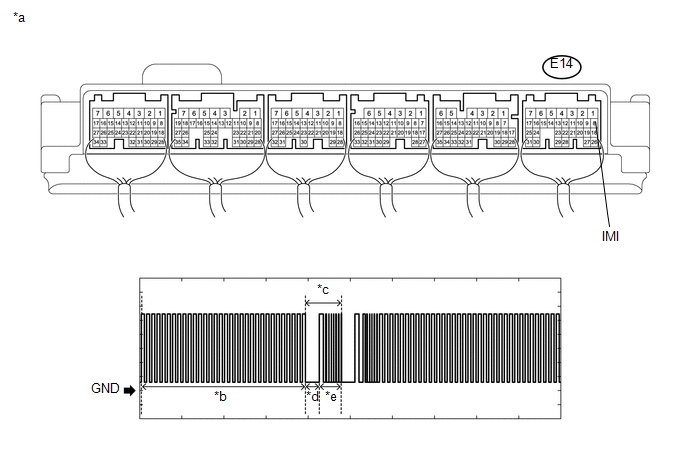 Text in Illustration
|
*a |
Component with harness connected (ECM) |
*b |
Waveform 1 |
|
*c |
Waveform 2 |
*d |
Approximately 160 ms |
|
*e |
Approximately 270 ms |
- |
- |
Measurement Condition:
|
Tester Connection |
Condition |
Tool Setting |
Specified Condition |
|---|---|---|---|
|
E14-8 (IMI) - Body ground |
Within 3 seconds of starter operation and initial combustion, or within 3 seconds of ignition switch first being turned to ON after cable disconnected and reconnected to negative (-) battery terminal |
2 V/DIV., 500 ms./DIV. |
Pulse generation (See waveform) |
|
Result |
Proceed to |
|---|---|
|
Normal waveform |
A |
|
Waveform 1 not output, or has abnormal wavelength or shape |
B |
|
Waveform 2 not output, or has abnormal wavelength or shape |
C |
| B | |
GO TO STEP 22 |
| C | |
GO TO STEP 23 |
|
|
16. |
CHECK ECM (TERMINAL IMO) |
(a) Using an oscilloscope, check the waveform.
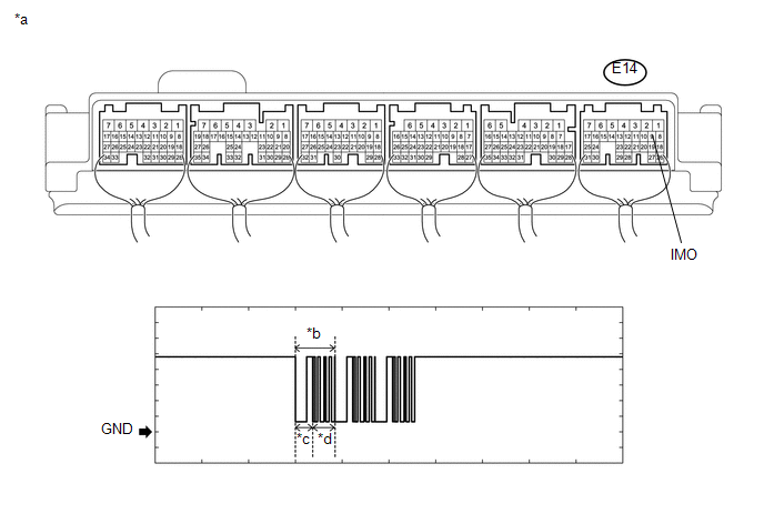 Text in Illustration
|
*a |
Component with harness connected (ECM) |
*b |
Waveform |
|
*c |
Approximately 160 ms |
*d |
Approximately 270 ms |
Measurement Condition:
|
Tester Connection |
Condition |
Tool Setting |
Specified Condition |
|---|---|---|---|
|
E14-9 (IMO) - Body ground |
Within 3 seconds of starter operation and initial combustion, or within 3 seconds of ignition switch first being turned to ON after cable disconnected and reconnected to negative (-) battery terminal |
2 V/DIV., 500 ms./DIV. |
Pulse generation (See waveform) |
|
Result |
Proceed to |
|---|---|
|
Normal waveform |
A |
|
Waveform not output, or has abnormal wavelength or shape |
B |
| B | |
GO TO STEP 19 |
|
|
17. |
REGISTER ECU COMMUNICATION ID |
(a) Register the communication ID between the transponder key ECU assembly and
ECM (See page ).
|
|
18. |
CHECK WHETHER ENGINE STARTS |
(a) Using a registered key, turn the ignition switch to ON.
(b) Check that the engine starts 5 seconds after the ignition switch was turned to ON.
OK:
Engine starts normally.
| OK | |
END (REGISTERED COMMUNICATION ID WAS DEFECTIVE) |
| NG | |
GO TO STEP 23 |
|
19. |
REPLACE ECM |
(a) Temporarily replace the ECM with a new one (See page
).
|
|
20. |
REGISTER ECU COMMUNICATION ID |
(a) Register the ECU communication ID (See page
).
|
|
21. |
CHECK WHETHER ENGINE STARTS |
(a) Using a registered key, turn the ignition switch to ON.
(b) Check that the engine starts 5 seconds after the ignition switch was turned to ON.
OK:
Engine starts normally.
| OK | |
END (ECM WAS DEFECTIVE) |
| NG | |
GO TO SFI SYSTEM |
|
22. |
CHECK HARNESS AND CONNECTOR (TRANSPONDER KEY ECU ASSEMBLY - ECM) |
(a) Disconnect the T10 transponder key ECU assembly connector.
(b) Disconnect the E14 ECM connector.
(c) Measure the resistance according to the value(s) in the table below.
Standard Resistance:
|
Tester Connection |
Condition |
Specified Condition |
|---|---|---|
|
T10-13 (EFIO) - E14-10 (IMI) |
Always |
Below 1 Ω |
|
T10-13 (EFIO) or E14-10 (IMI) - Body ground |
Always |
10 kΩ or higher |
| NG | |
REPAIR OR REPLACE HARNESS OR CONNECTOR |
|
|
23. |
REPLACE TRANSPONDER KEY ECU ASSEMBLY |
(a) Replace the transponder key ECU assembly with a new one (See page
).
NOTICE:
Key ID code registration is necessary when replacing the transponder key ECU
assembly, refer to Registration (See page ).
|
|
24. |
CHECK WHETHER ENGINE STARTS |
(a) Using a registered key, turn the ignition switch to ON.
(b) Check that the engine starts 5 seconds after the ignition switch was turned to ON.
OK:
Engine starts normally.
| OK | |
END (TRANSPONDER KEY ECU ASSEMBLY WAS DEFECTIVE) |
| NG | |
GO TO SFI SYSTEM |
 Engine does not Start because No Initial Combustion
DESCRIPTION
When a key is inserted into the ignition key cylinder, the transponder
key coil receives the key ID code and sends it to the transponder key ECU
assembly.
If an error i ...
 Key Cannot be Registered
DESCRIPTION
A maximum of 5 master key ID codes can be registered.
WIRING DIAGRAM
Refer to "B2780" (See page )
CAUTION / NOTICE / HINT
NOTICE:
If the transponder key ECU assembly is re ...
Other materials:
Removal
REMOVAL
CAUTION / NOTICE / HINT
HINT:
Use the same procedure for both the LH and RH sides.
The procedure described below is for the LH side.
PROCEDURE
1. REMOVE FRONT NO. 1 WHEEL OPENING EXTENSION PAD
Click here
2. SEPARATE FRONT FENDER LINER
(a) Remove the 2 ...
Installation
INSTALLATION
CAUTION / NOTICE / HINT
HINT:
Use the same procedure for the RH side and LH side.
The following procedure is for the LH side.
When installing a new front fender wheel opening moulding or quarter
panel wheel opening moulding, heat the vehicle body and front fender ...
How To Proceed With Troubleshooting
CAUTION / NOTICE / HINT
HINT:
Use the following procedure to troubleshoot the air conditioning system.
*: Use the Techstream.
PROCEDURE
1.
VEHICLE BROUGHT TO WORKSHOP
NEXT
...
