Toyota Tacoma (2015-2018) Service Manual: Replacement
REPLACEMENT
PROCEDURE
1. REPLACE STRAIGHT PIN
NOTICE:
It is not necessary to remove the straight pin unless it is being replaced.
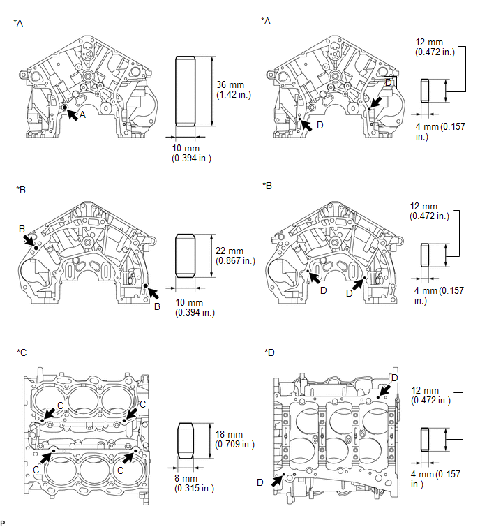
(a) Using a plastic-faced hammer, tap in new straight pins to the cylinder block.
 Text in Illustration
|
*A |
Front Side |
*B |
Rear Side |
|
*C |
Upper Side |
*D |
Lower Side |
Standard Protrusion:
|
Item |
Specified Condition |
|---|---|
|
Pin A |
22.5 to 23.5 mm (0.886 to 0.925 in.) |
|
Pin B |
10.5 to 11.5 mm (0.413 to 0.453 in.) |
|
Pin C |
8.5 to 9.5 mm (0.335 to 0.374 in.) |
|
Pin D |
5.5 to 6.5 mm (0.217 to 0.256 in.) |
2. REPLACE STUD BOLT
NOTICE:
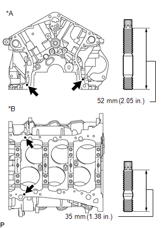
If a stud bolt is deformed or its threads are damaged, replace it.
|
(a) Using an E8 "TORX" socket wrench, install the stud bolts. Text in Illustration
Torque: 10 N·m {102 kgf·cm, 7 ft·lbf} |
|
 Inspection
INSPECTION
PROCEDURE
1. INSPECT CYLINDER BLOCK FOR WARPAGE
(a) Using a precision straightedge and feeler gauge, measure the warpage
of the contact surface of the cylinder head gasket ...
 Cylinder Head
...
Other materials:
Power windows*
The power windows can be opened/closed using the following switches.
Driver’s power window switches
Closing
Opening
One-touch opening (driver’s window
only)*
*: To stop the window partway, operate the switch in the opposite direction.
Front and rear passenger’s power
window swi ...
Calibration
CALIBRATION
1. DESCRIPTION
(a) After replacing the VSC relevant components or performing "Front wheel alignment
adjustment", clearing and reading the sensor calibration data are necessary.
(b) Follow the chart to perform calibration.
Replacing Parts
Necessary Op ...
System Description
SYSTEM DESCRIPTION
1. SEAT BELT WARNING SYSTEM DESCRIPTION
(a) Seat belt warning light operation for driver seat belt:
The seat belt warning light on the combination meter assembly illuminates, blinks
or turns off in accordance with the driver seat belt state, vehicle speed, shift
lever posit ...
