Toyota Tacoma (2015-2018) Service Manual: Installation
INSTALLATION
PROCEDURE
1. INSTALL CLUTCH PEDAL NO.1 CUSHION
(a) Install the clutch pedal No. 1 cushion to the clutch pedal sub-assembly.
2. INSTALL CLUTCH PEDAL SHAFT COLLAR
(a) Apply MP grease to the clutch pedal shaft collar.
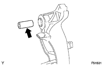 Text in Illustration
.png) |
MP grease |
(b) Install the clutch pedal shaft collar to the clutch pedal sub-assembly.
3. INSTALL CLUTCH PEDAL BUSH
(a) Apply MP grease to 2 new bushes.
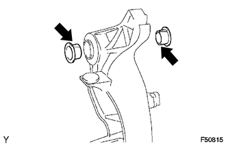 Text in Illustration
|
|
MP grease |
(b) Install the 2 bushes to the clutch pedal sub-assembly.
4. INSTALL CLUTCH PEDAL PAD
5. INSTALL CLUTCH PEDAL SPRING HOLDER
(a) Apply MP grease to the contact surface of the clutch pedal spring holder and clutch pedal support.
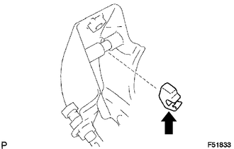 Text in Illustration
|
|
MP grease |
(b) Install the clutch pedal spring holder.
6. INSTALL CLUTCH PEDAL SUB-ASSEMBLY
(a) Install the clutch pedal sub-assembly to the clutch pedal support with the bolt and nut.
Torque:
34 N┬Ęm {350 kgf┬Ęcm, 25 ft┬Ęlbf}
HINT:
Install the bolt from the left side of the vehicle.
7. INSTALL TURN OVER SPRING SEAT COMPRESSION SPRING
(a) Apply MP grease to the contact surfaces of the clutch pedal sub-assembly and the compression spring.
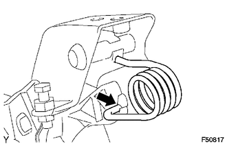 Text in Illustration
|
|
MP grease |
(b) Install the compression spring to the clutch pedal sub-assembly and the clutch pedal spring holder.
8. INSTALL CLUTCH MASTER CYLINDER ASSEMBLY
(See page .gif) )
)
 Adjustment
ADJUSTMENT
PROCEDURE
1. INSPECT AND ADJUST CLUTCH PEDAL
(a) Fold back the floor carpet.
(b) Check that the pedal height is correct.
Text in Illustration
*a
...
 Clutch Pedal Switch
On-vehicle Inspection
ON-VEHICLE INSPECTION
PROCEDURE
1. CHECK CLUTCH START SYSTEM
(a) Check that the engine does not start when the clutch pedal is released.
(b) Check that the engine starts ...
Other materials:
Main Body ECU Communication Stop Mode
DESCRIPTION
Detection Item
Symptom
Trouble Area
Main Body ECU Communication Stop Mode
Either condition is met:
Communication stop for "Main Body" is indicated on the "Communication
Bus Check" screen ...
Multimedia system types
Entune Audio
Entune Audio Plus
Refer to the ŌĆ£NAVIGATION SYSTEM OWNERŌĆÖS MANUALŌĆØ.
Entune Premium Audio
Refer to the ŌĆ£NAVIGATION SYSTEM OWNERŌĆÖS MANUALŌĆØ.
...
System Diagram
SYSTEM DIAGRAM
Communication Table
Sender
Receiver
Signal
Line
ECM
Millimeter Wave Radar Sensor Assembly
Cruise control operation signal
Accelerator pedal idle position signal
Accel overr ...
