Toyota Tacoma (2015-2018) Service Manual: Adjustment
ADJUSTMENT
PROCEDURE
1. INSPECT AND ADJUST CLUTCH PEDAL
(a) Fold back the floor carpet.
|
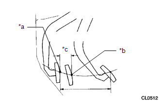
(b) Check that the pedal height is correct. Text in Illustration
Pedal height from floor panel: 178.1 to 188.1 mm (7.01 to 7.41 in.) |
|
(c) Adjust the pedal height.
(1) Loosen the lock nut and turn the clutch switch assembly until the height is correct. Tighten the lock nut.
Torque:
20 N·m {201 kgf·cm, 15 ft·lbf}
|
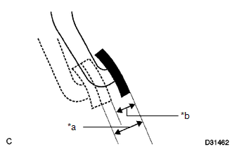
(d) Check the pedal free play and push rod play. Text in Illustration
HINT: Pay close attention to the change in resistance to distinguish between pedal free play and push rod play while performing the inspection. (1) Depress the clutch pedal until resistance is felt. (2) Measure the distance between the pedal's released position and the position in the previous step. Pedal free play: 5.0 to 15.0 mm (0.197 to 0.591 in.) (3) Release the pedal. Using your finger, gently press the pedal until resistance increases slightly. (4) Measure the distance between the pedal's released position and the position in the previous step. Push rod play at pedal top: 1.0 to 5.0 mm (0.0394 to 0.197 in.) |
|
(e) Adjust the pedal free play and push rod play.
HINT:
The push rod play can be adjusted by changing the length of the push rod. Pedal free play changes together with push rod play.
(1) Loosen the lock nut and turn the push rod until the pedal free play and push rod play are within the specified ranges.
NOTICE:
If pedal free play and push rod play are not within the standard range even after adjustment, inspect the related parts.
(2) Tighten the lock nut.
Torque:
12 N·m {120 kgf·cm, 9 ft·lbf}
(3) After adjusting the pedal free play and push rod play, check the pedal height.
|
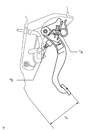
(f) Check the clutch release point. Text in Illustration
(1) Pull the parking brake lever and use wheel chocks to stabilize the vehicle. (2) Start the engine and run it at idle. (3) Without depressing the clutch pedal, slowly move the shift lever to R until the gears contact. (4) Gently depress the clutch pedal and measure the stroke distance from the point that the gear noise stops (release point) up to the full stroke end position. Standard distance: 25 mm (0.984 in.) or more If the result is not as specified, perform the following procedures.
|
|
 Removal
REMOVAL
PROCEDURE
1. REMOVE CLUTCH MASTER CYLINDER ASSEMBLY
(See page )
2. REMOVE TURN OVER SPRING SEAT COMPRESSION SPRING
(a) Remove the compression spring.
...
 Installation
INSTALLATION
PROCEDURE
1. INSTALL CLUTCH PEDAL NO.1 CUSHION
(a) Install the clutch pedal No. 1 cushion to the clutch pedal sub-assembly.
2. INSTALL CLUTCH PEDAL SHAFT COLLAR
(a) Apply MP grease t ...
Other materials:
Diagnostic Trouble Code Chart
DIAGNOSTIC TROUBLE CODE CHART
VSC System
DTC Code
Detection Item
See page
C1201
Engine Control System Malfunction
C1203
ECM Communication Circuit Malfunction
C120B
...
Inspection
INSPECTION
PROCEDURE
1. INSPECT FRONT OIL PUMP BODY SUB-ASSEMBLY
(a) Using a dial indicator, measure the inside diameter of the front
oil pump body sub-assembly bushing.
Maximum inside diameter:
38.138 mm (1.50 in.)
If the inside diameter is more than the maximum inside d ...
Air Outlet Damper Position Sensor Circuit (B1433/33)
DESCRIPTION
This sensor detects the position of the mode damper and sends the appropriate
signals to the air conditioning amplifier assembly. The position sensor is built
into the No. 1 air conditioning radiator damper servo sub-assembly (for mode switching).
DTC No.
DTC ...
