Toyota Tacoma (2015-2018) Service Manual: Removal
REMOVAL
PROCEDURE
1. REMOVE FRONT CONSOLE BOX
(See page .gif) )
)
2. DISCONNECT TRANSMISSION CONTROL CABLE ASSEMBLY
3. REMOVE TRANSMISSION CONTROL CABLE ASSEMBLY
|
(a) Remove the nut and clip and disconnect the transmission control cable assembly from the automatic transmission assembly. |
|
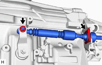
|
(b) Remove the nut and disconnect the transmission control cable assembly from the vehicle body. |
|
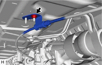
|
(c) Detach the clamp to disconnect the transmission control cable support from the transmission control cable clamp. |
|
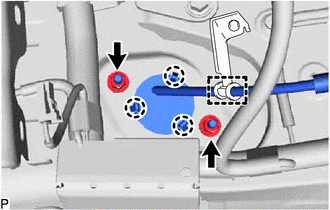
(d) Remove the 2 nuts and detach the 3 claws, and then pull out the transmission control cable assembly from the vehicle body.
 Installation
INSTALLATION
PROCEDURE
1. INSTALL TRANSMISSION CONTROL CABLE ASSEMBLY
(a) Install the transmission control cable assembly from outside the vehicle
body and attach the 3 claws of the cable retaine ...

Other materials:
Power Source Mode does not Change to ON (ACC)
DESCRIPTION
If the engine switch is pressed with the electrical key transmitter sub-assembly
in the cabin, the certification ECU (smart key ECU assembly) receives a signal and
changes the power source mode.
HINT:
When the cable is disconnected and reconnected to the negative (-) battery termi ...
Data List / Active Test
DATA LIST / ACTIVE TEST
1. DATA LIST
HINT:
Using the Techstream to read the Data List allows the values or states of switches,
sensors, actuators and other items to be read without removing any parts. This non-intrusive
inspection can be very useful because intermittent conditions or signals ...
How To Proceed With Troubleshooting
CAUTION / NOTICE / HINT
HINT:
Use these procedures to troubleshoot the lane departure alert system.
*: Use the Techstream.
PROCEDURE
1.
VEHICLE BROUGHT TO WORKSHOP
NEXT
...
