Toyota Tacoma (2015-2018) Service Manual: Inspection
INSPECTION
PROCEDURE
1. INSPECT OIL CLEARANCE
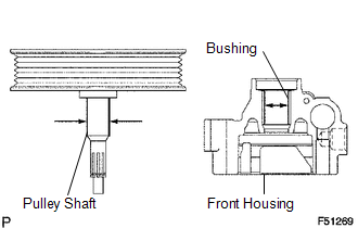
(a) Using a micrometer and caliper gauge, measure the oil seal clearance.
Standard clearance:
0.021 to 0.043 mm (0.0008 to 0.0017 in.)
Maximum clearance:
0.07 mm (0.0028 in.)
If it is greater than the maximum, replace the vane pump assembly.
2. INSPECT VANE PUMP ROTOR AND VANE PUMP PLATE
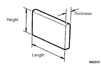
(a) Using a micrometer, measure the height, thickness and length of the vane plates.
Minimum height:
7.7 mm (0.303 in.)
Minimum thickness:
1.408 mm (0.0554 in.)
Minimum length:
11.993 mm (0.4722 in.)
|
(b) Using a feeler gauge, measure the clearance between a side face of the vane pump rotor groove and vane plate. Maximum clearance: 0.025 mm (0.0012 in.) If it is greater than the maximum, replace the vane pump assembly. |
|

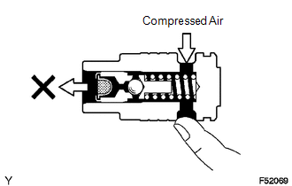
3. INSPECT FLOW CONTROL VALVE
.png)
(a) Coat the flow control valve with power steering fluid and check that it falls smoothly into the flow control valve hole under its own weight.
|
(b) Check the flow control valve for leakage. Close one of the holes and apply compressed air of 392 to 490 kPa (4 to 5 kgf/cm2, 57 to 71 psi) to the hole on the opposite side. Confirm that the air does not flow out of the end hole. If necessary, replace the vane pump assembly. |
|
4. INSPECT COMPRESSION SPRING
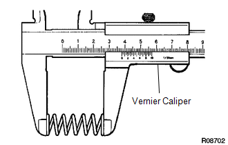
(a) Using vernier caliper, measure the free length of the spring.
Minimum free length:
36.9 mm (1.453 in.)
If it is not within the specification, replace the vane pump assembly.
5. INSPECT PRESSURE PORT UNION SUB-ASSEMBLY
(a) If the union seat in the pressure port union is badly damaged, it could cause fluid leakage, so replace the vane pump assembly.
 Removal
REMOVAL
PROCEDURE
1. PRECAUTION
NOTICE:
After turning the ignition switch off, waiting time may be required before disconnecting
the cable from the negative (-) battery terminal.
Therefore, mak ...
 Installation
INSTALLATION
PROCEDURE
1. INSTALL VANE PUMP
(a) Install the vane pump assembly with the 2 bolts.
Torque:
21 N·m {214 kgf·cm, 15 ft·lbf}
(b) Connect the oil pressure switch conne ...
Other materials:
Precaution
PRECAUTION
1. INITIALIZATION
NOTICE:
If the ECM is replaced, register the ECU communication ID for Engine
Immobiliser System (See page ).
Perform Registration (VIN registration) when replacing the ECM (See
page ).
HINT:
The engine learned value cannot be rese ...
System Description
SYSTEM DESCRIPTION
1. FRONT SEAT HEATER
(a) By operating the seat heater switch on the air conditioning control assembly,
the temperature can be controlled within the range of 36 to 42.2°C (96 to 108°F).
(b) The on/off status and heater level of each seat heater are indicated by the
respect ...
Freeze Frame Data
FREEZE FRAME DATA
1. DESCRIPTION
The ECM records vehicle and driving condition information as freeze frame data
the moment a DTC is stored. When troubleshooting, freeze frame data can be helpful
in determining whether the vehicle was moving or stationary, whether the engine
was warmed up or ...
