Toyota Tacoma (2015-2018) Service Manual: Removal
REMOVAL
PROCEDURE
1. PRECAUTION
NOTICE:
After turning the ignition switch off, waiting time may be required before disconnecting the cable from the negative (-) battery terminal.
Therefore, make sure to read the disconnecting the cable from the negative (-) battery terminal notices before proceeding with work.
Click here .gif)
2. DISCONNECT CABLE FROM NEGATIVE BATTERY TERMINAL
NOTICE:
When disconnecting the cable, some systems need to be initialized after the cable is reconnected.
Click here
3. REMOVE NO. 1 ENGINE UNDER COVER SUB-ASSEMBLY
4. REMOVE FAN AND GENERATOR V BELT
Click here
5. DRAIN POWER STEERING FLUID
6. DISCONNECT PRESSURE FEED TUBE ASSEMBLY
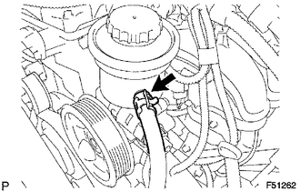
(a) Disengage the clip and disconnect the return hose.
|
(b) Remove the union bolt, then disconnect the pressure feed tube. |
|
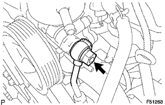
(c) Remove the gasket from the pressure feed tube.
7. REMOVE VANE PUMP
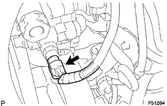
(a) Disconnect the oil pressure switch connector.
|
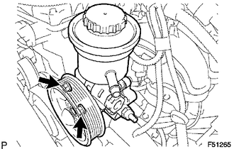
(b) Remove the 2 bolts and vane pump assembly. |
|
 Disassembly
DISASSEMBLY
PROCEDURE
1. FIX VANE PUMP
(a) Using SST, fix the vane pump assembly in a vise.
SST: 09630-00014
09631-00132
NOTICE:
When using a vise, do not overtighten it.
2. REMOVE VANE PUMP ...
 Inspection
INSPECTION
PROCEDURE
1. INSPECT OIL CLEARANCE
(a) Using a micrometer and caliper gauge, measure the oil seal clearance.
Standard clearance:
0.021 to 0.043 mm (0.0008 to 0.0017 in.)
Maximum cl ...
Other materials:
Components
COMPONENTS
ILLUSTRATION
*1
NO. 1 ENGINE UNDER COVER SUB-ASSEMBLY
*2
OIL PAN COVER SILENCER
*3
NO. 1 OIL PAN PLUG
-
-
N*m (kgf*cm, ft.*lbf): Specified torque
-
...
Seat belts
Make sure that all occupants are wearing their seat belts before driving the
vehicle.
■ Correct use of the seat belts
● Extend the shoulder belt so that it comes fully over the shoulder, but does
not come into contact with the neck or slide off the shoulder.
● Position the ...
Installation
INSTALLATION
PROCEDURE
1. INSTALL FRONT CONSOLE BOX (for Automatic Transmission)
(a) When installing a new front console box:
Text in Illustration
*a
Runner Portion
*b
Cut Off
(1) Usin ...
