Toyota Tacoma (2015-2018) Service Manual: Inspection
INSPECTION
PROCEDURE
1. INSPECT COUNTER GEAR
|
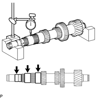
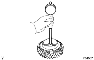
(a) Using a dial indicator and 2 V-blocks, measure the counter gear runout. Maximum runout: 0.03 mm (0.00118 in.) If the runout is more than the maximum, replace the counter gear. HINT: Measure the 3 areas shown in the illustration with the counter gear level. |
|
|
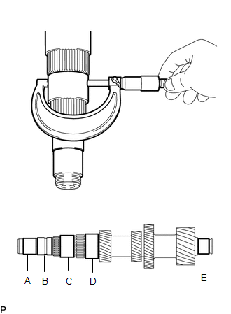
(b) Using a micrometer, measure the journal diameter of each counter gear journal, at the specified positions. Standard Journal Diameter:
Minimum Journal Diameter:
If the journal diameter is less than the minimum, replace the counter gear. |
|
2. INSPECT COUNTERSHAFT REVERSE GEAR
|
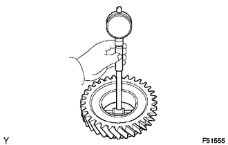
(a) Using a cylinder gauge, measure the inside diameter of the countershaft reverse gear. Standard inside diameter: 51.015 to 51.040 mm (2.0085 to 2.0094 in.) Maximum inside diameter: 51.040 mm (2.0094 in.) If the inside diameter is more than the maximum, replace the countershaft reverse gear. |
|
3. INSPECT COUNTERSHAFT 1ST SPEED GEAR
|
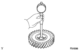
(a) Using a cylinder gauge, measure the inside diameter of the countershaft 1st speed gear. Standard inside diameter: 54.015 to 54.040 mm (2.1266 to 2.1275 in.) Maximum inside diameter: 54.040 mm (2.1275 in.) If the inside diameter is more than the maximum, replace the countershaft 1st speed gear. |
|
4. INSPECT COUNTERSHAFT 2ND SPEED GEAR
|
(a) Using a cylinder gauge, measure the inside diameter of the countershaft 2nd speed gear. Standard inside diameter: 60.015 to 60.040 mm (2.3628 to 2.3637 in.) Maximum inside diameter: 60.040 mm (2.3637 in.) If the inside diameter is more than the maximum, replace the countershaft 2nd speed gear. |
|
5. INSPECT NO. 4 TRANSMISSION HUB SLEEVE
|
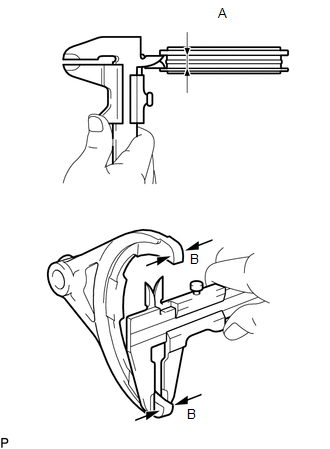
(a) Using a vernier caliper, measure the width of the No. 4 transmission hub sleeve groove (A) and the thickness of the 2 claw parts of the No. 4 gear shift fork (B), and calculate the clearance. Standard clearance (A - B): 0.30 to 0.50 mm (0.012 to 0.019 in.) If the clearance is outside the specification, replace the No. 4 transmission hub sleeve and No. 4 gear shift fork. |
|
6. INSPECT NO. 1 TRANSMISSION HUB SLEEVE
|
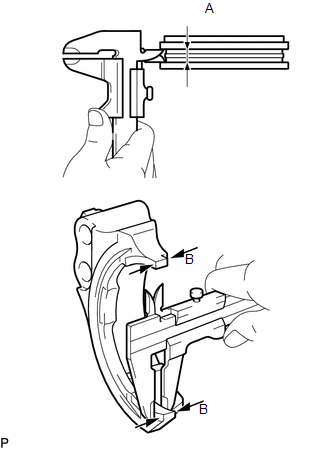
(a) Using a vernier caliper, measure the width of the No. 1 transmission hub sleeve groove (A) and the thickness of the 2 claw parts of the No. 1 gear shift fork (B), and calculate the clearance. Standard clearance (A - B): 0.15 to 0.35 mm (0.006 to 0.013 in.) If the clearance is outside the specification, replace the No. 1 transmission hub sleeve and No. 1 gear shift fork. |
|
|
(b) Check the sliding condition between the No. 1 transmission clutch hub and No. 1 transmission hub sleeve. |
|
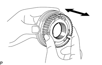
(c) Check that the splines of the No. 1 transmission hub sleeve are not worn.
7. INSPECT NO. 1 SYNCHRONIZER RING SET
|
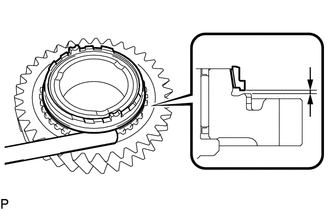
(a) Using a feeler gauge, measure the clearance between the No. 1 synchronizer ring set and countershaft 1st speed gear. Standard clearance: 0.83 to 1.77 mm (0.0327 to 0.0696 in.) Minimum clearance: 0.83 mm (0.0326 in.) If the clearance is less than the minimum, replace the No. 1 synchronizer ring set. |
|
(b) Coat the countershaft 1st speed gear cone with gear oil.
|
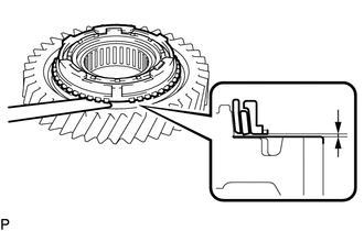
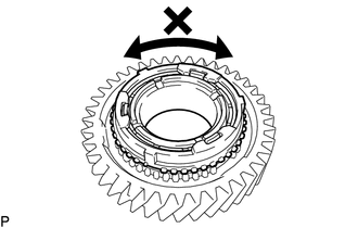
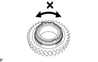
(c) Check the braking effect of the synchronizer ring. (1) Turn the synchronizer ring in both directions while pushing it against the countershaft 1st speed gear cone. Check that the ring locks in both directions. If the No. 1 synchronizer ring set turns, replace it. |
|
8. INSPECT NO. 2 SYNCHRONIZER RING SET
|
(a) Using a feeler gauge, measure the clearance between the No. 2 synchronizer ring set and countershaft 2nd speed gear. Standard clearance: 0.88 to 1.72 mm (0.0347 to 0.0677 in.) Minimum clearance: 0.88 mm (0.0347 in.) If the clearance is less than the minimum, replace the No. 2 synchronizer ring set. |
|
(b) Coat the countershaft 2nd speed gear cone with gear oil.
|
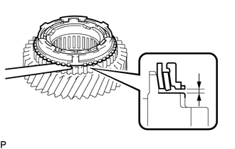
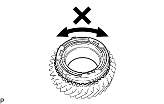
(c) Check the braking effect of the No. 2 synchronizer ring set. (1) Turn the synchronizer ring in both directions while pushing it against the countershaft 2nd speed gear cone. Check that the ring locks in both directions. If the No. 2 synchronizer ring set turns, replace it. |
|
9. INSPECT REVERSE SYNCHRONIZER RING
|
(a) Using a feeler gauge, measure the clearance between the No. 2 synchronizer ring set and countershaft 2nd speed gear. Standard clearance: 0.65 to 1.35 mm (0.0256 to 0.0531 in.) Minimum clearance: 0.65 mm (0.0256 in.) If the clearance is less than the minimum, replace the reverse synchronizer ring. |
|
|
(b) Check the braking effect of the reverse synchronizer ring. (1) Turn the synchronizer ring in both directions while pushing it against the countershaft reverse gear cone. Check that the ring locks in both directions. If the reverse synchronizer ring turns, replace it. |
|
 Disassembly
DISASSEMBLY
PROCEDURE
1. INSPECT COUNTERSHAFT REVERSE GEAR THRUST CLEARANCE
(a) Using a dial indicator, measure the countershaft reverse gear thrust
clearance.
Standard clearance: ...
 Input Shaft
...
Other materials:
Removal
REMOVAL
PROCEDURE
1. PLACE FRONT WHEELS FACING STRAIGHT AHEAD
2. REMOVE FRONT WHEELS
3. REMOVE FRONT UPPER FENDER APRON SEAL
Click here
4. REMOVE NO. 2 ENGINE UNDER COVER SUB-ASSEMBLY (w/ Off Road Package)
5. REMOVE NO. 1 ENGINE UNDER COVER SUB-ASSEMBLY
6. REMOVE FRONT DIFFERENTIAL CARRI ...
Abbreviations Used In Manual
ABBREVIATIONS USED IN MANUAL
Abbreviations
Meaning
ABS
Anti-Lock Brake System
A/C
Air Conditioner
AC
Alternating Current
ACC
Accessory
ACIS
...
Disassembly
DISASSEMBLY
PROCEDURE
1. REMOVE CYLINDER BOOT
(a) Using a screwdriver, remove the 4 cylinder boots from the caliper.
2. REMOVE FRONT DISC BRAKE PISTON
(a) Prepare a wooden plate to hold the pistons.
(b) Place the plate between the pistons and insert a pad into one side.
...
