Toyota Tacoma (2015-2018) Service Manual: Disassembly
DISASSEMBLY
PROCEDURE
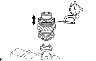
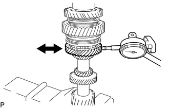
1. INSPECT COUNTERSHAFT REVERSE GEAR THRUST CLEARANCE
|
(a) Using a dial indicator, measure the countershaft reverse gear thrust clearance. Standard clearance: 0.150 to 0.300 mm (0.0060 to 0.0118 in.) If the clearance is outside the specification, replace the countershaft reverse gear, reverse gear bearing inner race or No. 4 transmission clutch hub. HINT: Replace the part or parts determined to be the most likely cause of the problem. |
|
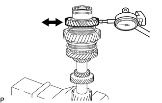
2. INSPECT COUNTERSHAFT REVERSE GEAR RADIAL CLEARANCE
|
(a) Using a dial indicator, measure the countershaft reverse gear radial clearance. Standard clearance: 0.015 to 0.065 mm (0.0006 to 0.0026 in.) If the clearance is outside the specification, replace the countershaft reverse gear, reverse gear bearing inner race or needle roller bearing. HINT: Replace the part or parts determined to be the most likely cause of the problem. |
|
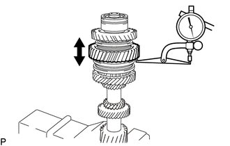
3. INSPECT COUNTERSHAFT 1ST SPEED GEAR THRUST CLEARANCE
|
(a) Using a dial indicator, measure the countershaft 1st speed gear thrust clearance. Standard clearance: 0.150 to 0.480 mm (0.0060 to 0.0188 in.) If the clearance is outside the specification, replace the countershaft 1st speed gear, clutch hub or counter gear. HINT: Replace the part or parts determined to be the most likely cause of the problem. |
|
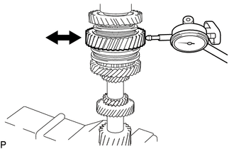
4. INSPECT COUNTERSHAFT 1ST SPEED GEAR RADIAL CLEARANCE
|
(a) Using a dial indicator, measure the countershaft 1st speed gear radial clearance. Standard clearance: 0.015 to 0.067 mm (0.0006 to 0.0026 in.) If the clearance is outside the specification, replace the countershaft 1st speed gear, 1st gear needle roller bearing or shaft. HINT: Replace the part or parts determined to be the most likely cause of the problem. |
|
5. INSPECT COUNTERSHAFT 2ND SPEED GEAR THRUST CLEARANCE
|
(a) Using a dial indicator, measure the countershaft 2nd speed gear thrust clearance. Standard clearance: 0.150 to 0.480 mm (0.0060 to 0.0188 in.) If the clearance is outside the specification, replace the countershaft 2nd speed gear, clutch hub or counter gear. HINT: Replace the part or parts determined to be the most likely cause of the problem. |
|
6. INSPECT COUNTERSHAFT 2ND SPEED GEAR RADIAL CLEARANCE
|
(a) Using a dial indicator, measure the countershaft 2nd speed gear radial clearance. Standard clearance: 0.015 to 0.067 mm (0.0006 to 0.0026 in.) If the clearance is outside the specification, replace the countershaft 2nd speed gear, 2nd gear needle roller bearing or shaft. HINT: Replace the part or parts determined to be the most likely cause of the problem. |
|
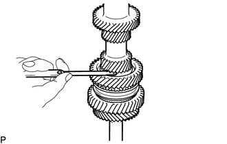
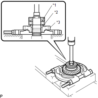
7. REMOVE REAR COUNTER GEAR BEARING SNAP RING
|
(a) Using a snap ring expander, remove the rear counter gear bearing snap ring from the counter gear. |
|
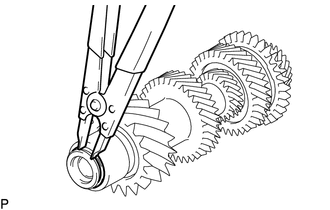
8. REMOVE REAR COUNTER GEAR BEARING OR ROLLER
|
(a) Using SST, remove the rear counter gear bearing or roller (inner races) from the counter gear. SST: 09950-40011 09951-04010 09952-04010 09953-04010 09954-04010 09955-04071 09957-04010 09958-04011 SST: 09950-60010 09951-00320 |
|
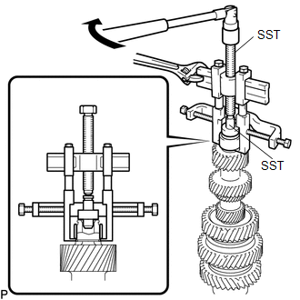
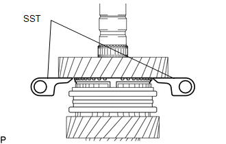
9. REMOVE COUNTERSHAFT REVERSE GEAR
|
(a) Using SST and a press, remove the front counter gear bearing or roller, center countershaft bearing, reverse gear bearing inner race and countershaft reverse gear from the counter gear. Text in Illustration
SST: 09555-55010 SST: 09950-60010 09951-00320 SST: 09950-70010 09951-07100 NOTICE: Support the counter gear by hand so that it does not fall. |
|
10. REMOVE REVERSE GEAR BEARING
(a) Remove the reverse gear bearing from the counter gear.
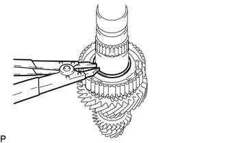
11. REMOVE REVERSE SHIFT RESTRICT BALL
(a) Remove the reverse shift restrict ball from the counter gear.
12. REMOVE REVERSE SYNCHRONIZER RING
(a) Remove the reverse synchronizer ring from the counter gear.
13. REMOVE NO. 3 SYNCHROMESH SHIFTING KEY SPRING
(a) Remove the No. 3 synchromesh shifting key spring from the counter gear.
14. REMOVE NO. 3 SYNCHROMESH SHIFTING KEY
(a) Remove the 2 No. 3 synchromesh shifting keys from the counter gear.
15. REMOVE NO. 4 TRANSMISSION HUB SLEEVE
(a) Remove the No. 4 transmission hub sleeve from the No. 4 transmission clutch hub.
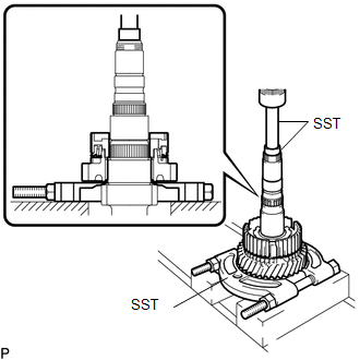
16. REMOVE NO. 4 TRANSMISSION CLUTCH HUB
(a) Using SST and a press, remove the No. 4 transmission clutch hub and countershaft 1st speed gear from the counter gear.

SST: 09555-55010
SST: 09950-60010
09951-00320
SST: 09950-70010
09951-07100
NOTICE:
- Do not insert SST deep inside the gear, as this may damage the synchronizer ring.
- Use SST in the position shown in the illustration.
17. REMOVE 1ST GEAR NEEDLE ROLLER BEARING
(a) Remove the 1st gear needle roller bearing from the counter gear.
18. REMOVE NO. 1 SYNCHRONIZER RING SET
(a) Remove the No. 1 synchronizer ring set from the counter gear.
19. REMOVE NO. 1 TRANSMISSION HUB SLEEVE
(a) Remove the No. 1 transmission hub sleeve from the No. 1 transmission clutch hub.
20. REMOVE NO. 1 SYNCHROMESH SHIFTING KEY
(a) Remove the 3 No. 1 synchromesh shifting keys from the No. 1 transmission clutch hub.
21. REMOVE NO. 1 CLUTCH HUB SHAFT SNAP RING
|
(a) Using a snap ring expander, remove the No. 1 clutch hub shaft snap ring from the counter gear. |
|
22. REMOVE NO. 1 TRANSMISSION CLUTCH HUB
|
(a) Using SST and a press, remove the countershaft 2nd speed gear, No. 2 synchronizer ring set and No. 1 transmission clutch hub from the counter gear. SST: 09555-55010 SST: 09950-60010 09951-00320 SST: 09950-70010 09951-07100 |
|
23. REMOVE 2ND GEAR NEEDLE ROLLER BEARING
(a) Remove the 2nd gear needle roller bearing from the counter gear.
 Components
COMPONENTS
ILLUSTRATION
ILLUSTRATION
...
 Inspection
INSPECTION
PROCEDURE
1. INSPECT COUNTER GEAR
(a) Using a dial indicator and 2 V-blocks, measure the counter gear runout.
Maximum runout:
0.03 mm (0.00118 in.)
If the runout is ...
Other materials:
Power windows*
The power windows can be opened/closed using the following switches.
Driver’s power window switches
Closing
Opening
One-touch opening (driver’s window
only)*
*: To stop the window partway, operate the switch in the opposite direction.
Front and rear passenger’s power
window swi ...
Precaution
PRECAUTION
1. IGNITION SWITCH EXPRESSION
HINT:
The type of ignition switch used on this model differs depending on the specifications
of the vehicle. The expressions listed in the table below are used in this section.
Expression
Ignition Switch (Position)
Engin ...
Motor Malfunction (C1427)
DESCRIPTION
DTC No.
Detection Item
DTC Detection Condition
Trouble Area
C1427
Motor Malfunction
Actuator pump motor does not operate properly.
Brake actuator assembly (Ground circuit)
Brak ...
