Toyota Tacoma (2015-2018) Service Manual: Image from Camera for Rear View Monitor is Abnormal
DESCRIPTION
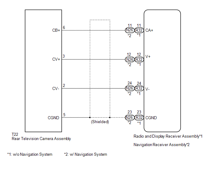
The display signal of the rear television camera assembly is transmitted to the radio and display receiver assembly*1 or navigation receiver assembly*2.
- *1: w/o Navigation System
- *2: w/ Navigation System
WIRING DIAGRAM
PROCEDURE
|
1. |
CONFIRM MODEL |
(a) Choose the model to be inspected.
Result|
Result |
Proceed to |
|---|---|
|
w/o Navigation System |
A |
|
w/ Navigation System |
B |
| B | .gif) |
GO TO STEP 5 |
|
.gif)
|
2. |
CHECK HARNESS AND CONNECTOR (RADIO AND DISPLAY RECEIVER ASSEMBLY - REAR TELEVISION CAMERA ASSEMBLY) |
(a) Disconnect the R32 radio and display receiver assembly connector.
(b) Disconnect the T22 rear television camera assembly connector.
(c) Measure the resistance according to the value(s) in the table below.
Standard Resistance:
|
Tester Connection |
Condition |
Specified Condition |
|---|---|---|
|
R32-11 (CA+) - T22-6 (CB+) |
Always |
Below 1 ╬ę |
|
R32-12 (V+) - T22-3 (CV+) |
Always |
Below 1 ╬ę |
|
R32-24 (V-) - T22-2 (CV-) |
Always |
Below 1 ╬ę |
|
R32-23 (CGND) - T22-5 (CGND) |
Always |
Below 1 ╬ę |
|
R32-11 (CA+) - Body ground |
Always |
10 k╬ę or higher |
|
R32-12 (V+) - Body ground |
Always |
10 k╬ę or higher |
|
R32-24 (V-) - Body ground |
Always |
10 k╬ę or higher |
|
R32-23 (CGND) - Body ground |
Always |
10 k╬ę or higher |
(d) Reconnect the radio and display receiver assembly connector.
| NG | |
REPAIR OR REPLACE HARNESS OR CONNECTOR |
|
|
3. |
INSPECT RADIO AND DISPLAY RECEIVER ASSEMBLY |
(a) Disconnect the radio and display receiver assembly connector.
|
(b) Measure the resistance according to the value(s) in the table below. Standard Voltage:
|
|
(c) Measure the voltage according to the value(s) in the table below.
Standard Voltage:
|
Tester Connection |
Switch Condition |
Specified Condition |
|---|---|---|
|
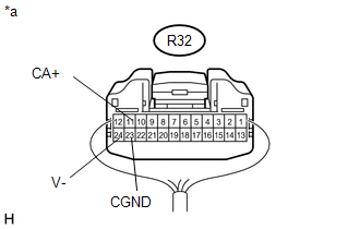
R32-11 (CA+) - R32-23 (CGND) |
Ignition switch ON, shift lever in R |
5.5 to 7.05 V |
|
*a |
Component with harness connected (Radio and Display Receiver Assembly) |
| NG | |
REPLACE RADIO AND DISPLAY RECEIVER ASSEMBLY |
|
|
4. |
INSPECT REAR TELEVISION CAMERA ASSEMBLY |
(a) Reconnect the rear television camera assembly connector.
(b) Check the waveform of the rear television camera assembly using an oscilloscope.
 Text in Illustration
|
*a |
Component with harness connected (Radio and Display Receiver Assembly) |
HINT:
A waterproof connector is used for the rear television camera assembly. Therefore, inspect the waveform at the radio and display receiver assembly with the connector connected.
Measurement Condition|
Item |
Content |
|---|---|
|
Terminal No. (Symbol) |
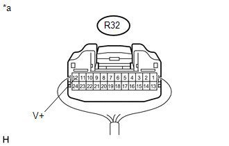
R32-12 (V+) - R32-24 (V-) |
|
Tool Setting |
200 mV/DIV., 50 ╬╝sec./DIV. |
|
Condition |
Waveform 1: Ignition switch ON, shift lever in R Waveform 2: Ignition switch ON, shift lever in R, screen blacked out by covering camera lens |
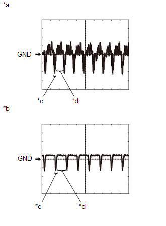
OK:
Waveform is as shown in the illustration.
HINT:
The video waveform changes according to the image sent by the rear television camera assembly.
Text in Illustration|
*a |
Waveform 1 |
|
*b |
Waveform 2 |
|
*c |
Synchronized Signal |
|
*d |
Video Waveform |
| OK | |
PROCEED TO NEXT SUSPECTED AREA SHOWN IN PROBLEM SYMPTOMS TABLE |
| NG | |
REPLACE REAR TELEVISION CAMERA ASSEMBLY |
|
5. |
CHECK HARNESS AND CONNECTOR (NAVIGATION RECEIVER ASSEMBLY - REAR TELEVISIONCAMERA ASSEMBLY) |
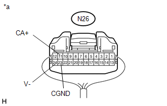
(a) Disconnect the N26 navigation receiver assembly connector.
(b) Disconnect the T22 rear television camera assembly connector.
(c) Measure the resistance according to the value(s) in the table below.
Standard Resistance:
|
Tester Connection |
Condition |
Specified Condition |
|---|---|---|
|
N26-11 (CA+) - T22-6 (CB+) |
Always |
Below 1 ╬ę |
|
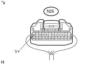
N26-12 (V+) - T22-3 (CV+) |
Always |
Below 1 ╬ę |
|
N26-24 (V-) - T22-2 (CV-) |
Always |
Below 1 ╬ę |
|
N26-23 (CGND) - T22-5 (CGND) |
Always |
Below 1 ╬ę |
|
N26-11 (CA+) - Body ground |
Always |
10 k╬ę or higher |
|
N26-12 (V+) - Body ground |
Always |
10 k╬ę or higher |
|
N26-24 (V-) - Body ground |
Always |
10 k╬ę or higher |
|
N26-23 (CGND) - Body ground |
Always |
10 k╬ę or higher |
(d) Reconnect the navigation receiver assembly connector.
| NG | |
REPAIR OR REPLACE HARNESS OR CONNECTOR |
|
|
6. |
INSPECT NAVIGATION RECEIVER ASSEMBLY |
(a) Disconnect the navigation receiver assembly connector.
|
(b) Measure the resistance according to the value(s) in the table below. Standard Voltage:
|
|
(c) Measure the voltage according to the value(s) in the table below.
Standard Voltage:
|
Tester Connection |
Switch Condition |
Specified Condition |
|---|---|---|
|
N26-11 (CA+) - N26-23 (CGND) |
Ignition switch ON, shift lever in R |
5.5 to 7.05 V |
|
*a |
Component with harness connected (Navigation Receiver Assembly) |
| NG | |
REPLACE NAVIGATION RECEIVER ASSEMBLY |
|
|
7. |
INSPECT REAR TELEVISION CAMERA ASSEMBLY |
(a) Reconnect the rear television camera assembly connector.
(b) Check the waveform of the rear television camera assembly using an oscilloscope.
 Text in Illustration
|
*a |
Component with harness connected (Navigation Receiver Assembly) |
HINT:
A waterproof connector is used for the rear television camera assembly. Therefore, inspect the waveform at the navigation receiver assembly with the connector connected.
Measurement Condition|
Item |
Content |
|---|---|
|
Terminal No. (Symbol) |
N26-12 (V+) - N26-24 (V-) |
|
Tool Setting |
200 mV/DIV., 50 ╬╝sec./DIV. |
|
Condition |
Waveform 1: Ignition switch ON, shift lever in R Waveform 2: Ignition switch ON, shift lever in R, screen blacked out by covering camera lens |
OK:
Waveform is as shown in the illustration.
HINT:
The video waveform changes according to the image sent by the rear television camera assembly.
Text in Illustration|
*a |
Waveform 1 |
|
*b |
Waveform 2 |
|
*c |
Synchronized Signal |
|
*d |
Video Waveform |
| OK | |
PROCEED TO NEXT SUSPECTED AREA SHOWN IN PROBLEM SYMPTOMS TABLE |
| NG | |
REPLACE REAR TELEVISION CAMERA ASSEMBLY |
 Reverse Signal Circuit
DESCRIPTION
The radio and display receiver assembly*1 or navigation receiver assembly*2 receives
a reverse signal from the park/neutral position switch*3 or the back-up light switch
assembly*4.
...
 Television Camera
Components
COMPONENTS
ILLUSTRATION
Installation
INSTALLATION
PROCEDURE
1. INSTALL REAR TELEVISION CAMERA ASSEMBLY
(a) Install the rear television camera assembly with the 2 bolts.
Torque ...
Other materials:
Camper information
This information has been prepared in accordance with regulation issued by
the National Highway Traffic Safety Administration of the U.S. Department of Transportation.
It provides the purchasers and/or prospective purchasers of Toyota vehicles with
information on truck-camper loading. Your Toy ...
Trailer Socket
Components
COMPONENTS
ILLUSTRATION
Removal
REMOVAL
PROCEDURE
1. REMOVE TRAILER SOCKET
(a) Disconnect the connector.
(b) Disengage the 2 clips to remove the trailer socket.
Install ...
USB port/AUX port
Connect an iPod, USB memory device or portable audio player to the USB port/AUX
port as indicated below. Select ÔÇťiPodÔÇŁ, ÔÇťUSBÔÇŁ or ÔÇťAUXÔÇŁ on the ÔÇťSelect Audio SourceÔÇŁ
screen and the device can be operated via multimedia system.
Connecting using the USB port/AUX port
■ iPod
...
