Toyota Tacoma (2015-2018) Service Manual: Television Camera
Components
COMPONENTS
ILLUSTRATION
Installation
INSTALLATION
PROCEDURE
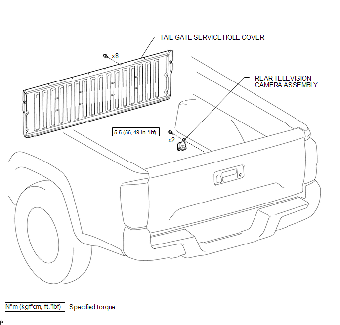
1. INSTALL REAR TELEVISION CAMERA ASSEMBLY
(a) Install the rear television camera assembly with the 2 bolts.
Torque:
5.5 N┬Ęm {56 kgf┬Ęcm, 49 in┬Ęlbf}
(b) Connect the connector.
2. INSTALL TAIL GATE SERVICE HOLE COVER
(See page .gif) )
)
3. INSTALL TAIL GATE PROTECTOR
(See page )
Removal
REMOVAL
PROCEDURE
1. REMOVE TAIL GATE PROTECTOR
(See page .gif) )
)
2. REMOVE TAIL GATE SERVICE HOLE COVER
(See page )
3. REMOVE REAR TELEVISION CAMERA ASSEMBLY
|
(a) Disconnect the connector. |
|
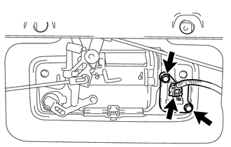
(b) Remove the 2 bolts and rear television camera assembly.
 Image from Camera for Rear View Monitor is Abnormal
DESCRIPTION
The display signal of the rear television camera assembly is transmitted to the
radio and display receiver assembly*1 or navigation receiver assembly*2.
*1: w/o Navigation Syste ...

Other materials:
High Power Supply Voltage Malfunction (C1417)
DESCRIPTION
If a malfunction is detected in the power supply circuit, the skid control ECU
(housed in the master cylinder solenoid) stores this DTC and the fail-safe function
prohibits ABS/VSC/TRAC operation.
This DTC is stored when the IG1 terminal voltage deviates from the DTC detection
co ...
Problem Symptoms Table
PROBLEM SYMPTOMS TABLE
HINT:
Use the table below to help determine the cause of problem symptoms.
If multiple suspected areas are listed, the potential causes of the symptoms
are listed in order of probability in the "Suspected Area" column of the
table. Check each sy ...
Problem Symptoms Table
PROBLEM SYMPTOMS TABLE
HINT:
Use the table below to help determine the cause of problem symptoms.
If multiple suspected areas are listed, the potential causes of the symptoms
are listed in order of probability in the "Suspected Area" column of the
table. Check each sy ...
