Toyota Tacoma (2015-2018) Service Manual: How To Use This Manual
General Information
GENERAL INFORMATION
1. GENERAL DESCRIPTION
(a) This manual is written in accordance with SAE J2008.
(1) Diagnosis
(2) Removing / Installing, Replacing, Disassembling / Reassembling, Checking and Adjusting
(3) Final Inspection
(b) The following procedures are omitted from this manual. However, these procedures must be performed.
(1) Use a jack or lift to perform operations.
(2) Clean all removed parts.
(3) Perform a visual check.
2. INDEX
(a) An alphabetical INDEX section is provided at the end of the manual as a reference to help you find the item to be repaired.
3. PREPARATION
(a) Use of Special Service Tools (SST) and Special Service Materials (SSM) may be required, depending on the repair procedure. Be sure to use SST and SSM when they are required and follow the working procedures properly. A list of SST and SSM is in the "Preparation" section of this manual.
4. REPAIR PROCEDURES
(a) A component illustration is placed under the title where necessary.
(b) Non-reusable parts, grease application areas, precoated parts and torque specifications are noted in the component illustrations.
- The following illustration is an example.
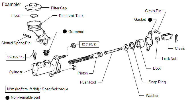
(c) Torque specifications, grease application areas and non-reusable parts are emphasized in the procedures.
HINT:
There are cases where such information can only be explained by using an illustration. In these cases, torque, oil and other information are described in the illustration.
(d) Only items with key points are described in the text. What to do and other details are explained using illustrations next to the text. Both the text and illustrations are accompanied by standard values and notices.
|
Illustration |
What to do and where to do it |
|
Task heading |
What work will be performed |
|
Explanation text |
|
(e) Illustrations of similar vehicle models are sometimes used. In these cases, minor details may be different from the actual vehicle.
(f) Procedures are presented in a step-by-step format.
5. SERVICE SPECIFICATIONS
(a) SPECIFICATIONS are presented in boldface text throughout the manual. The specifications are also found in the "Service Specifications" section for reference.
6. TERM DEFINITIONS
|
CAUTION |
Possibility of injury to you or other people. |
|
NOTICE |
Possibility of damage to components being repaired. |
|
HINT |
Provides additional information to help you perform repairs. |
7. INTERNATIONAL SYSTEM OF UNITS
(a) The units used in this manual comply with the International System of Units (SI UNIT) standard. Units from the metric system and the English system are also provided.
- Example:
Torque:
30 N·m {310 kgf·cm, 22 ft·lbf}
 Electronic Circuit Inspection Procedure
ELECTRONIC CIRCUIT INSPECTION PROCEDURE
1. BASIC INSPECTION
(a) WHEN MEASURING RESISTANCE OF ELECTRONIC PARTS
(1) Unless otherwise stated, all resistance measurements should be made at an
ambient ...
 Identification Information
Vehicle Identification And Serial Numbers
VEHICLE IDENTIFICATION AND SERIAL NUMBERS
1. VEHICLE IDENTIFICATION NUMBER
(a) The vehicle identification number is stamped on the vehicle body and on ...
Other materials:
High Pitched Horn
Components
COMPONENTS
ILLUSTRATION
Removal
REMOVAL
PROCEDURE
1. REMOVE RADIATOR GRILLE
Click here
2. REMOVE HIGH PITCHED HORN ASSEMBLY
(a) Disconnect the connector.
(b) Remove the bolt and high pitched horn assembly.
Inspection
...
Diagnostic Trouble Code Chart
DIAGNOSTIC TROUBLE CODE CHART
Main Body ECU (Multiplex Network Body ECU)
DTC Code
Detection Item
See page
B1206
P/W Master Switch Communication Stop
B1273
Sliding Roof ECU Communication Stop
...
Manual transmission
■ Shifting the shift lever
6-speed models
Fully depress the clutch pedal before operating the shift lever, and then release
it slowly.
5-speed models
Fully depress the clutch pedal before operating the shift lever, and then release
it slowly.
■Maximum allowable speed
Obse ...
