Toyota Tacoma (2015-2018) Service Manual: Removal
REMOVAL
PROCEDURE
1. REMOVE FUEL PUMP ASSEMBLY (for High Pressure)
(See page .gif) )
)
2. REMOVE NO. 2 FUEL PIPE SUB-ASSEMBLY
(a) Loosen the 2 union nuts and remove the No. 2 fuel pipe sub-assembly from the fuel delivery pipe RH and fuel delivery pipe sub-assembly LH.
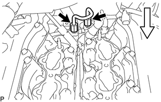 Text in Illustration
.png) |
Front |
3. REMOVE FUEL DELIVERY PIPE ASSEMBLY LH (FUEL PRESSURE SENSOR)
NOTICE:
- Do not remove the fuel pressure sensor from the fuel delivery pipe assembly LH.
- If a fuel pressure sensor is removed, replace the fuel delivery pipe assembly LH (fuel pressure sensor) with a new one.
|
(a) Disconnect the 2 connectors. |
|
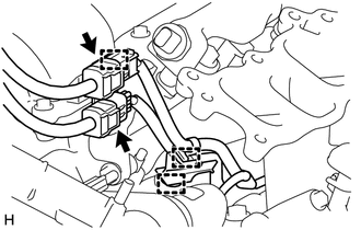
(b) Disengage the 3 clamps and disconnect the No. 6 engine wire and No. 7 engine wire.
|
(c) Disconnect the fuel pressure sensor connector. NOTICE: Do not pull the wire harness of the fuel pressure sensor excessively. |
|
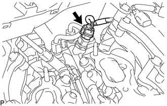
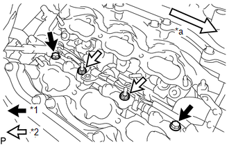
(d) Remove the bolt.
 Text in Illustration
|
|
Front |
(e) Disengage the clamp and disconnect the No. 7 engine wire.
|
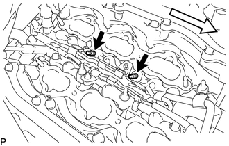
(f) Remove the 2 bolts and 2 nuts. Text in Illustration
|
|
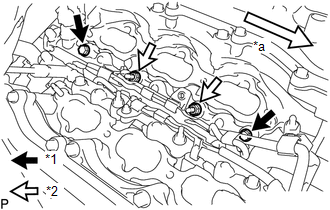
(g) Using an E8 "TORX" socket wrench, remove the 2 stud bolts from the cylinder head LH.
 Text in Illustration
|
|
Front |
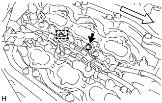
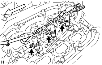
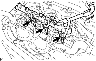
(h) With the connectors still connected, disconnect the fuel delivery pipe assembly LH.
 Text in Illustration
|
|
Front |
NOTICE:
- Make sure that the fuel delivery pipe is disconnected from the fuel delivery pipe assembly LH.
- Be extremely careful not to touch or strike the tips of the fuel injector assemblies.
- Pull and remove the fuel delivery pipe in a straight line without tilting it.
(i) Disconnect the 3 fuel injector connectors and remove the No. 7 engine wire.
4. REMOVE FUEL DELIVERY PIPE RH
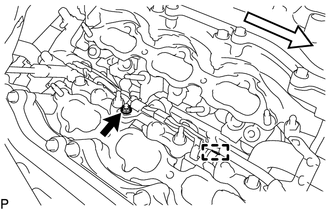
(a) Remove the bolt.
 Text in Illustration
|
|
Front |
(b) Disengage the clamp and disconnect the No. 6 engine wire.
|
(c) Remove the 2 bolts and 2 nuts. Text in Illustration
|
|
(d) With the connectors still connected, disconnect the fuel delivery pipe RH.
 Text in Illustration
|
|
Front |
NOTICE:
- Be extremely careful not to touch or strike the tips of the fuel injector assemblies.
- Pull and remove the fuel delivery pipe in a straight line without tilting it.
(e) Disconnect the 3 injector connectors and remove the No. 6 engine wire.
5. REMOVE FUEL INJECTOR ASSEMBLY
|
(a) Fix the fuel delivery pipe in a vise between aluminum plates. NOTICE:
|
|
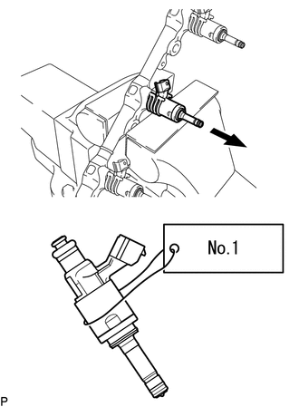
(b) Remove the fuel injector assemblies from the fuel delivery pipe assembly LH and fuel delivery pipe RH.
NOTICE:
- When removing an injector, pull the injector straight out to avoid damaging the O-ring seal surfaces of the fuel delivery pipe assembly LH and fuel delivery pipe RH.
- After removing the fuel injector assembly, check that the O-ring, No. 1 fuel injector back-up ring and No. 3 fuel injector back-up ring are not remaining on the fuel delivery pipe. If any of the parts remain on the fuel delivery pipe, remove them.
- Attach a label to the removed fuel injector assembly to distinguish it from other cylinders.
(c) Remove the nozzle holder clamps from the injectors.
(d) Using needle-nose pliers, remove the No. 3 fuel injector back-up ring from the fuel injector assembly.
NOTICE:
Do not damage the part contacting the O-ring.
(e) Remove the O-ring and No. 1 fuel injector back-up ring.
(f) Remove the C-rings and injector vibration insulators from the fuel injector assemblies.
6. REMOVE FUEL INJECTOR SEAL
|
(a) Using the tips of a pair of needle nose pliers, pinch and pull one of the fuel injector seals at several points to stretch it. Repeat this for the other fuel injector seal. NOTICE:
|
|
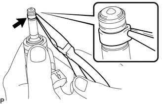
(b) Remove the fuel injector seal from the fuel injector assembly.
 Inspection
INSPECTION
PROCEDURE
1. INSPECT FUEL INJECTOR ASSEMBLY
NOTICE:
This inspection aims at inspecting the fuel injectors for opens or shorts, because
the fuel injectors of this vehicle are a high-pr ...
 Installation
INSTALLATION
CAUTION / NOTICE / HINT
HINT:
Perform "Inspection After Repairs" after replacing the fuel injector assembly
(See page ).
PROCEDURE
1. INSTALL FUEL INJECTOR SEAL
...
Other materials:
How To Proceed With Troubleshooting
CAUTION / NOTICE / HINT
HINT:
Use the following procedures to troubleshoot the steering lock system.
*: Use the Techstream.
PROCEDURE
1.
VEHICLE BROUGHT TO WORKSHOP
NEXT
...
Yaw Rate Sensor Malfunction (C1436)
DESCRIPTION
The skid control ECU (master cylinder solenoid) receives signals from the yaw
rate and acceleration (airbag sensor assembly) via the CAN communication system.
The airbag sensor assembly has a built-in yaw rate and acceleration sensor and
detects the vehicle's condition using 2 ...
Control Module Communication Bus OFF (U0073,U0100,U0114,U0123,U0124,U0126)
DESCRIPTION
The skid control ECU (master cylinder solenoid) receives the signals from the
ECM, steering angle sensor (spiral cable with sensor sub-assembly), 4 wheel drive
control ECU*, and yaw rate and acceleration sensor (airbag sensor assembly) via
the CAN communication system.
*: ...
