Toyota Tacoma (2015-2018) Service Manual: Headlight Dimmer Switch Circuit
DESCRIPTION
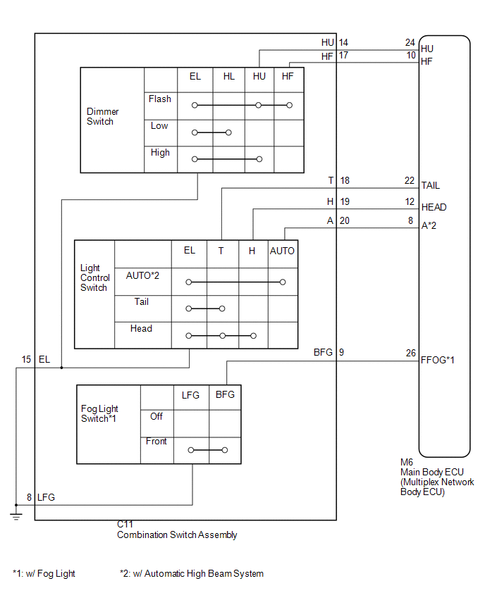
The main body ECU (multiplex network body ECU) receives the following switch information:
- Light control switch position is off (DRL OFF), tail, head or AUTO (DRL).
- Dimmer switch position is high, low or high flash (pass).
- Front fog light switch position is on or off.
WIRING DIAGRAM
CAUTION / NOTICE / HINT
NOTICE:
If the main body ECU (multiplex network body ECU) is replaced, refer to Registration
(See page .gif) ).*1
).*1
- *1: w/ Smart Key System
PROCEDURE
|
1. |
READ VALUE USING TECHSTREAM |
(a) Connect the Techstream to the DLC3.
(b) Turn the ignition switch to ON.
(c) Turn the Techstream on.
(d) Enter the following menus: Body Electrical / Main Body / Data List.
(e) According to the display on the Techstream, read the Data List.
Main Body|
Tester Display |
Measurement Item/Range |
Normal Condition |
Diagnostic Note |
|---|---|---|---|
|
Dimmer SW |
Dimmer switch high position signal/ON or OFF |
ON: Dimmer switch in high or high flash (pass) position OFF: Dimmer switch in low position |
- |
|
Passing Light SW |
Dimmer switch high flash (pass) position signal/ON or OFF |
ON: Dimmer switch in high flash (pass) position OFF: Dimmer switch not in high flash (pass) position |
- |
|
Front Fog Light SW |
Front fog light switch signal/ON or OFF |
ON: Front fog light switch ON OFF: Front fog light switch off |
w/ Fog Light |
|
Auto Light SW |
Light control switch AUTO position signal/ON or OFF |
ON: Light control switch in AUTO position OFF: Light control switch not in AUTO position |
w/ Automatic High Beam System |
|
Head Light SW |
Light control switch head position signal/ON or OFF |
ON: Light control switch in head position OFF: Light control switch not in head position |
- |
|
Tail Light SW |
Light control switch tail position signal/ON or OFF |
ON: Light control switch in tail or head position OFF: Light control switch in neither tail nor head position |
- |
OK:
Normal conditions listed above are displayed.
| OK | .gif) |
PROCEED TO NEXT SUSPECTED AREA SHOWN IN PROBLEM SYMPTOMS TABLE |
|
.gif)
|
2. |
INSPECT HEADLIGHT DIMMER SWITCH ASSEMBLY |
HINT:
Inspect the items that did not change as a result of monitoring the Data List.
(a) Remove the headlight dimmer switch assembly (See page
).
|
(b) Measure the resistance according to the value(s) in the table below. Standard Resistance: Light Control Switch
OK: Headlight dimmer switch assembly is normal Text in Illustration
|
|
| NG | |
REPLACE HEADLIGHT DIMMER SWITCH |
|
|
3. |
CHECK HARNESS AND CONNECTOR (MAIN BODY ECU (MULTIPLEX NETWORK BODY ECU) - HEADLIGHT DIMMER SWITCH ASSEMBLY |
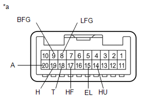
(a) Disconnect the C11 headlight dimmer switch assembly connector.
(b) Disconnect the M6 main body ECU (multiplex network body ECU) connector.
(c) Measure the resistance according to the value(s) in the table below.
Standard Resistance:
|
Tester Connection |
Condition |
Specified Condition |
|---|---|---|
|
C11-9 (BFG) - M6-26 (FFOG) |
Always |
Below 1 Ω |
|
C11-14 (HU) - M6-24 (HU) |
Always |
Below 1 Ω |
|
C11-17 (HF) - M6-10 (HF) |
Always |
Below 1 Ω |
|
C11-18 (T) - M6-22 (TAIL) |
Always |
Below 1 Ω |
|
C11-19 (H) - M6-12 (HEAD) |
Always |
Below 1 Ω |
|
C11-20 (A) - M6-8 (A) |
Always |
Below 1 Ω |
|
C11-9 (BFG) - Body ground |
Always |
10 kΩ or higher |
|
C11-14 (HU) - Body ground |
Always |
10 kΩ or higher |
|
C11-17 (HF) - Body ground |
Always |
10 kΩ or higher |
|
C11-18 (T) - Body ground |
Always |
10 kΩ or higher |
|
C11-19 (H) - Body ground |
Always |
10 kΩ or higher |
|
C11-20 (A) - Body ground |
Always |
10 kΩ or higher |
|
C11-15 (EL) - Body ground |
Always |
Below 1 Ω |
|
C11-8 (LFG) - Body ground |
Always |
Below 1 Ω |
| OK | |
REPLACE MAIN BODY ECU (MULTIPLEX NETWORK BODY ECU) |
| NG | |
REPAIR OR REPLACE HARNESS OR CONNECTOR |
 Daytime Running Light Relay Circuit
DESCRIPTION
The main body ECU (multiplex network body ECU) controls the daytime running lights.
WIRING DIAGRAM
CAUTION / NOTICE / HINT
NOTICE:
Inspect the fuses for circuits related to ...
 Door Courtesy Switch Circuit
DESCRIPTION
The main body ECU (multiplex network Body ECU) receives a door open or closed
signal from each door courtesy light switch.
WIRING DIAGRAM
CAUTION / NOTICE / HINT
NOTICE:
R ...
Other materials:
Brake System Malfunction (C1A50)
DESCRIPTION
When the pre-collision system is operating, the millimeter wave radar sensor
assembly sends brake control signals to the skid control ECU (master cylinder solenoid)*1
or skid control ECU (brake actuator assembly)*2.
If the millimeter wave radar sensor assembly receives a vehicle st ...
Installation
INSTALLATION
PROCEDURE
1. INSTALL AIR CONDITIONING UNIT ASSEMBLY
(a) Temporary install the air conditioning unit assembly.
(b) Insert the bracket hook into the holes of the reinforcement bracket, and
temporary install the instrument panel reinforcement assembly.
(c) Install the instrument p ...
Noise Filter(for 2gr-fks)
Components
COMPONENTS
ILLUSTRATION
Removal
REMOVAL
PROCEDURE
1. DISCONNECT CABLE FROM NEGATIVE BATTERY TERMINAL
2. REMOVE V-BANK COVER
(See page )
3. REMOVE AIR CLEANER ASSEMBLY
(See page )
4. REMOVE RADIO SETTING CONDENSER
(a) Disconnect the connector.
(b) Remove the tape an ...
