Toyota Tacoma (2015-2018) Service Manual: Fuel Sender Open Detected (B1500)
DESCRIPTION
This DTC is output when the combination meter assembly detects a fuel sender gauge assembly malfunction.
|
DTC No. |
DTC Detection Condition |
Trouble Area |
|---|---|---|
|
B1500 |
When either of the following conditions is detected:
|
|
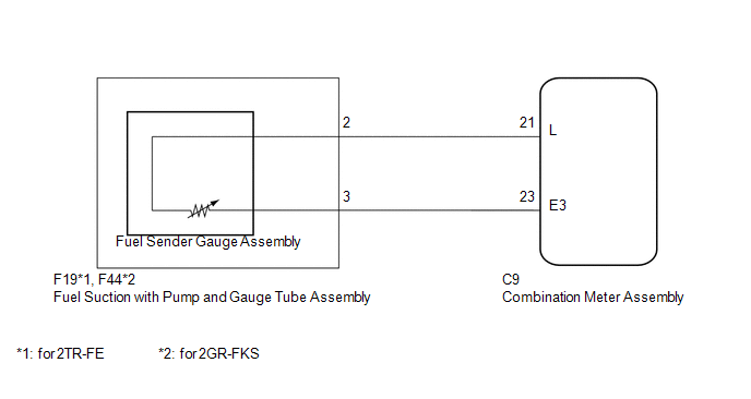
WIRING DIAGRAM
PROCEDURE
|
1. |
READ VALUE USING TECHSTREAM (FUEL INPUT) |
(a) Connect the Techstream to the DLC3.
(b) Turn the ignition switch to ON.
(c) Turn the Techstream on.
(d) Enter the following menus: Body Electrical / Combination Meter / Data List.
(e) According to the display on the Techstream, read the Data List.
Combination Meter|
Tester Display |
Measurement Item/Range |
Normal Condition |
Diagnostic Note |
|---|---|---|---|
|
Fuel Input |
Fuel input signal/ Min.: 0, Max.: 127.5 |
Current fuel level displayed |
Unit: Liter |
|
Result |
Proceed to |
|---|---|
|
Fuel level data can be displayed on the Techstream and DTC B1500 is output |
A |
|
Fuel level data cannot be displayed on the Techstream |
B |
| A | .gif) |
REPLACE COMBINATION METER ASSEMBLY |
|
.gif)
|
2. |
INSPECT FUEL SENDER GAUGE ASSEMBLY |
|
(a) Disconnect the combination meter assembly connector. |
|
(b) Measure the resistance according to the value(s) in the table below.
Standard Resistance:
|
Tester Connection |
Condition |
Specified Condition |
|---|---|---|
|
C9-21 (L) - C9-23 (E3) |
Always |
13.5 to 414.5 Ω |
|
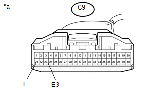
*a |
Front view of wire harness connector (to Combination Meter Assembly) |
| OK | |
REPLACE COMBINATION METER ASSEMBLY |
|
|
3. |
CHECK HARNESS AND CONNECTOR (COMBINATION METER ASSEMBLY - FUEL SUCTION WITH PUMP AND GAUGE TUBE ASSEMBLY) |
(a) Disconnect the C9 combination meter assembly connector.
(b) Disconnect the F19 (for 2TR-FE) or F44 (2GR-FKS) fuel suction with pump and gauge tube assembly connector.
(c) Measure the resistance according to the value(s) in the table below.
Standard Resistance (for 2TR-FE):
|
Tester Connection |
Condition |
Specified Condition |
|---|---|---|
|
C9-21 (L) - F19-2 |
Always |
Below 1 Ω |
|
C9-21 (L) or F19-2 - Body ground |
Always |
10 kΩ or higher |
|
C9-23 (E3) - F19-3 |
Always |
Below 1 Ω |
|
C9-23 (E3) or F19-3 - Body ground |
Always |
10 kΩ or higher |
Standard Resistance (for 2GR-FKS):
|
Tester Connection |
Condition |
Specified Condition |
|---|---|---|
|
C9-21 (L) - F44-2 |
Always |
Below 1 Ω |
|
C9-21 (L) or F44-2 - Body ground |
Always |
10 kΩ or higher |
|
C9-23 (E3) - F44-3 |
Always |
Below 1 Ω |
|
C9-23 (E3) or F44-3 - Body ground |
Always |
10 kΩ or higher |
| NG | |
REPAIR OR REPLACE HARNESS OR CONNECTOR |
|
|
4. |
INSPECT FUEL SENDER GAUGE ASSEMBLY |
(a) Remove the fuel sender gauge assembly.
- for 2TR-FE: (See page
.gif) )
) - for 2GR-FKS: (See page )
(b) Inspect the fuel sender gauge assembly.
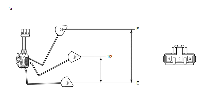 Text in Illustration
|
*a |
Component without harness connected (Fuel Sender Gauge Assembly) |
- |
- |
(c) Measure the resistance according to the value(s) in the table below.
Standard Resistance:
for: 2TR-FE|
Tester Connection |
Float Level |
Float Position (mm (in.)) |
Specified Condition |
|---|---|---|---|
|
1 - 2 |
F |
181.9 to 193.9 (7.161 to 7.633) |
3.0 to 5.0 Ω |
|
1/2 |
90.9 to 102.9 (3.578 to 4.051) |
55.6 to 62.4 Ω |
|
|
E |
0 (0) |
109.0 to 111.0 Ω |
|
Tester Connection |
Float Level |
Float Position (mm (in.)) |
Specified Condition |
|---|---|---|---|
|
1 - 2 |
F |
181.9 to 193.9 (7.161 to 7.633) |
13.5 to 16.5 Ω |
|
1/2 |
90.9 to 102.9 (3.578 to 4.051) |
201.0 to 224.0 Ω |
|
|
E |
0 (0) |
405.5 to 414.5 Ω |
|
Result |
Proceed to |
|---|---|
|
OK |
A |
|
NG (for 2TR-FE) |
B |
|
NG (for 2GR-FKS) |
C |
| B | |
REPLACE FUEL SENDER GAUGE ASSEMBLY (for 2TR-FE) |
| C | |
REPLACE FUEL SENDER GAUGE ASSEMBLY (for 2GR-FKS) |
|
|
5. |
INSPECT FUEL SUCTION PUMP AND GAUGE TUBE ASSEMBLY |
|
(a) Remove the fuel suction pump and gauge tube assembly.
|
|
(b) Measure the resistance according to the value(s) in the table below.
Standard Resistance:
|
Tester Connection |
Condition |
Specified Condition |
|---|---|---|
|
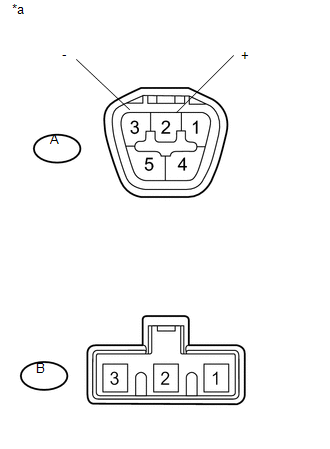
A-2 - B-2 |
Always |
Below 1 Ω |
|
A-3 - B-1 |
|
*a |
Component without harness connected (Fuel Suction with Pump and Gauge Tube Assembly) |
|
Result |
Proceed to |
|---|---|
|
OK |
A |
|
NG (for 2TR-FE) |
B |
|
NG (for 2GR-FKS) |
C |
| A | |
REPLACE COMBINATION METER ASSEMBLY |
| B | |
REPLACE FUEL SUCTION WITH PUMP AND GAUGE TUBE ASSEMBLY (for 2TR-FE) |
| C | |
REPLACE FUEL SUCTION W/PUMP & GAUGE TUBE ASSEMBLY (for 2GR-FKS) |
 On-vehicle Inspection
ON-VEHICLE INSPECTION
PROCEDURE
1. INSPECT SPEEDOMETER
(a) Check speedometer operation.
NOTICE:
The meter ECU receives the vehicle speed signal from the skid control
ECU via CAN commu ...
 Open in Turn Signal Circuit (B1507,B1508)
DESCRIPTION
This DTC is stored when the combination meter assembly detects an open in a turn
signal light circuit, a short in a turn signal light circuit, or a short in the
hazard warning light c ...
Other materials:
Noise Occurs or Sound Skips when Portable Player Plays
CAUTION / NOTICE / HINT
HINT:
Perform this check with the portable player volume set at an appropriate
level.
Make sure that there are no obstructions between the portable player
and navigation receiver assembly that may block signals, and that the portable
player and navig ...
Voice Recognition Microphone Disconnected (B1579)
DESCRIPTION
The radio and display receiver assembly and telephone microphone assembly are
connected to each other using the microphone connection detection signal lines.
This DTC is stored when a microphone connection detection signal line is disconnected.
DTC Code
DTC Det ...
Manual Shifting Test
MANUAL SHIFTING TEST
1. PERFORM MANUAL SHIFTING TEST
HINT:
Using this test, it can be determined whether a problem is in an electrical
circuit or if it is a mechanical problem in the transmission.
If any abnormalities are found in the following test, the problem is
in the tran ...
